




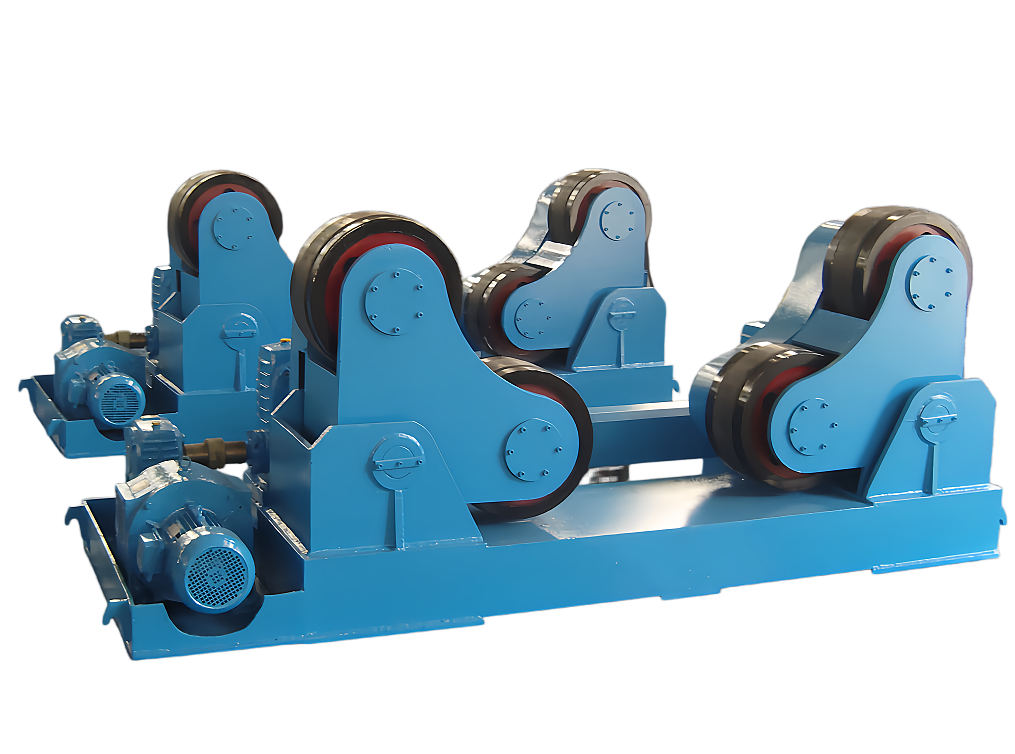
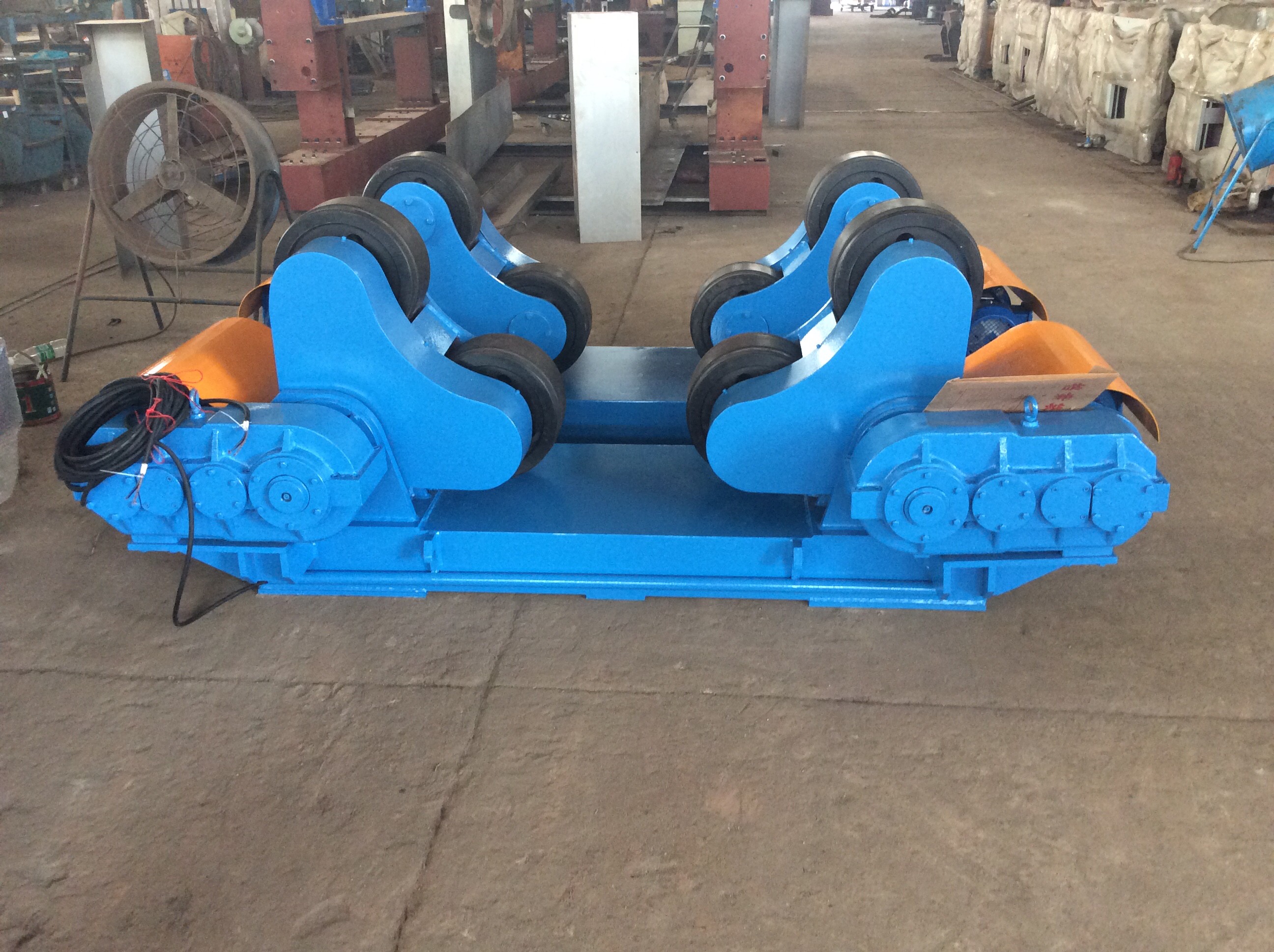
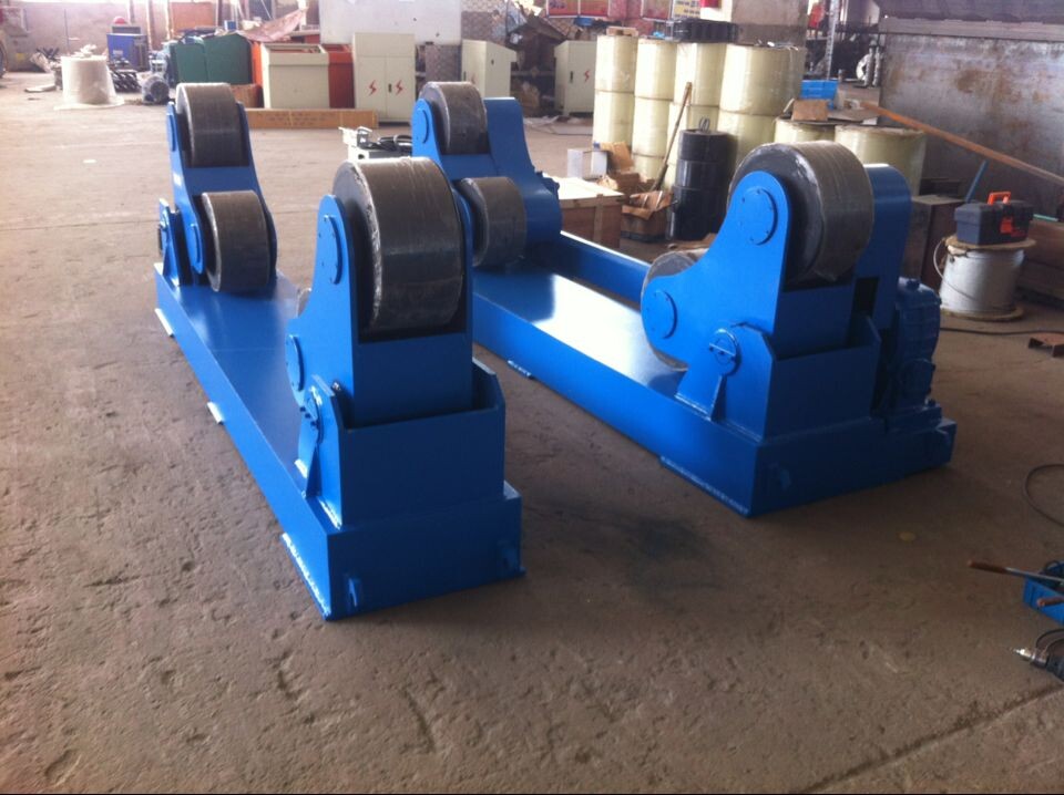
Self aligning welding rotator
1.1 System Composition
A complete welding rotator system consists of three primary components:
Active (driven) rotator – equipped with a motor and reduction drive to provide rotational power
Passive (idle) rotator – provides support and follows the rotation of the driven unit
Control system – enables precise speed regulation for optimal welding conditions
Full-range Machinery & Customized Non-standard Solutions
Authorized Certificates & Independent R&D Patents
Over 10 Years Global Export & Worldwide Project Cases
Navigation

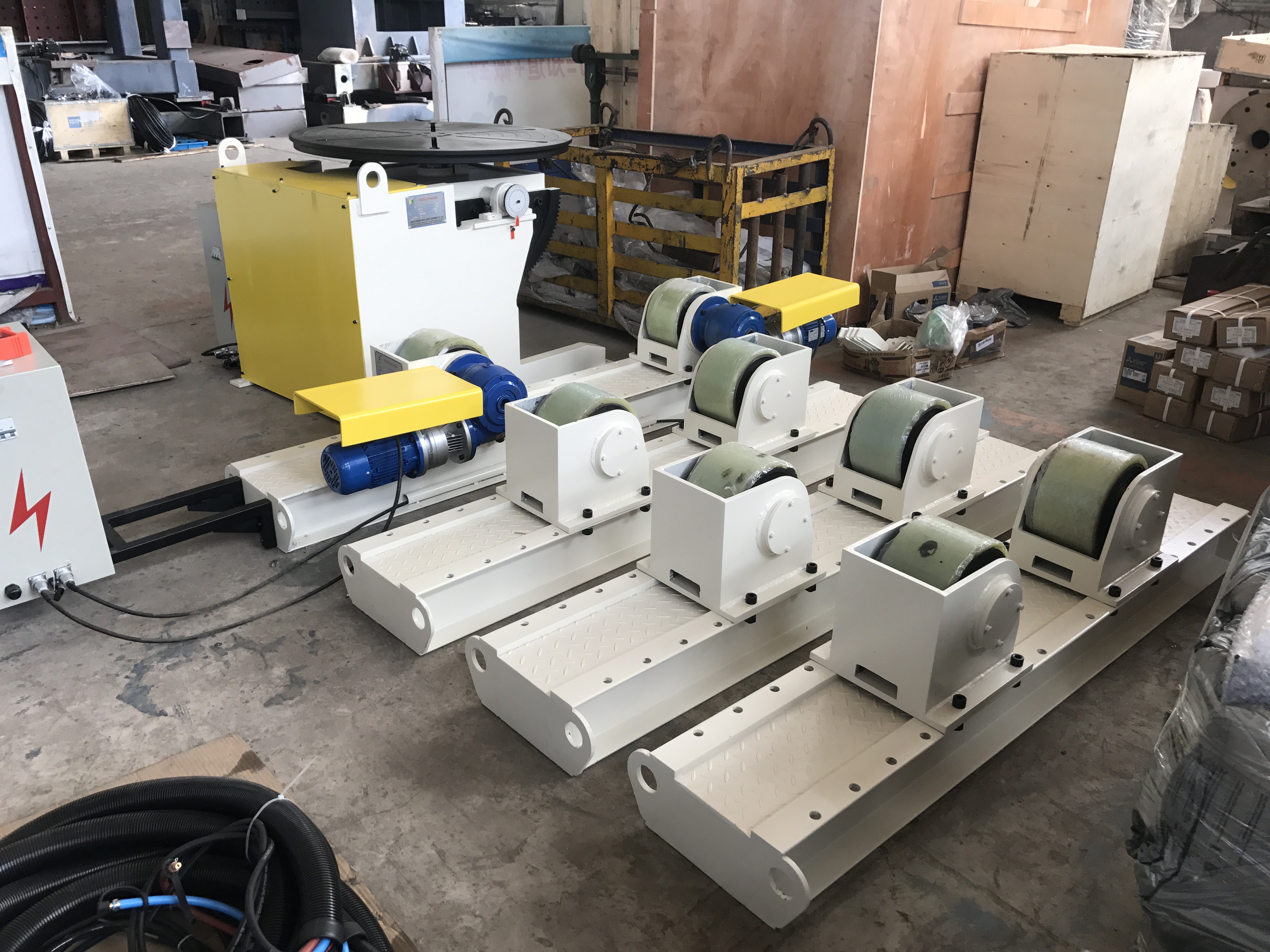
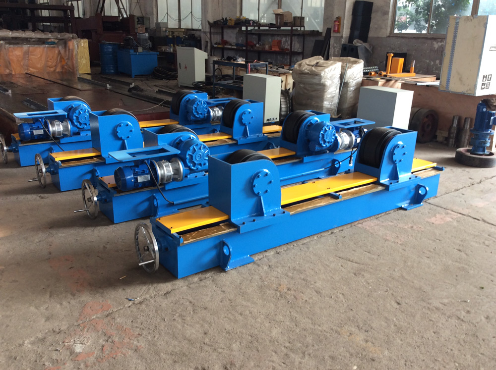
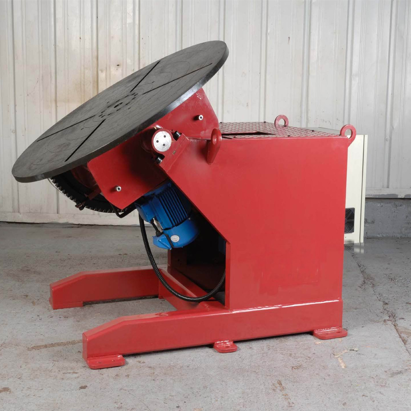
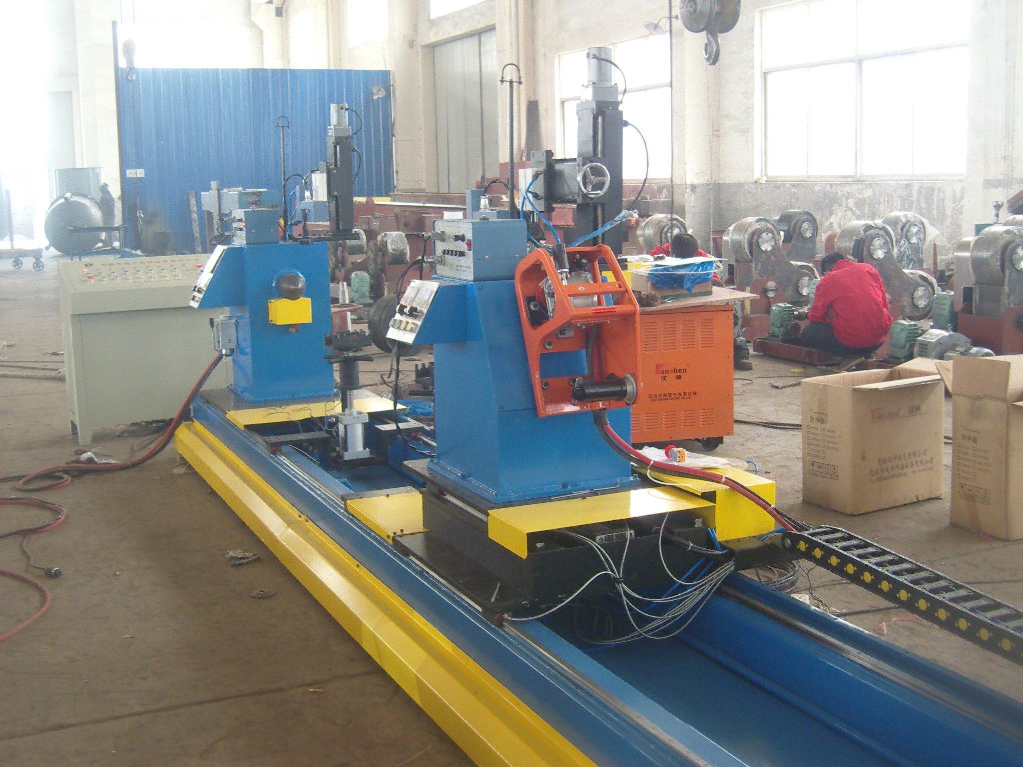
Self aligning welding rotator Description
1.Product Introduction: Self-Aligning Welding Rotator
The self-aligning welding rotator is a specialized auxiliary device designed to support and precisely rotate cylindrical workpieces during welding operations.
1.1 System Composition
A complete welding rotator system consists of three primary components:
Active (driven) rotator – equipped with a motor and reduction drive to provide rotational power
Passive (idle) rotator – provides support and follows the rotation of the driven unit
Control system – enables precise speed regulation for optimal welding conditions
1.2 Core Function
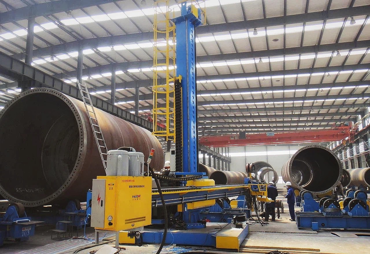
The rotator is primarily used to rotate cylindrical workpieces such as pipes, pressure vessels, and tanks, positioning the weld joint at the ideal angle for high-quality welding.
1.3 Key Applications
Butt welding of large-diameter pipes
Fabrication of pressure vessels and boilers
Circumferential and longitudinal seam welding on cylindrical components
1.4 Major Advantages
Enhanced welding quality – stable, uniform rotation ensures consistent weld bead formation
Improved productivity – reduces handling and repositioning time for continuous welding cycles
Reduced labor intensity – eliminates manual turning and traditional lifting methods, simplifying operation
Operational safety – provides secure support and stable rotation for heavy workpieces
2.Technical parameter for Self aligning welding rotator
3.Characters for Self aligning welding rotator:
3.1. Welding rotator consist of One drive unit and One idler unit.
3.2. Automatic welding rotator Remote hand control box with functions, FWD turning,REV turning,Speed setting.
3.3. Pipe Welding rotator rotating speed is 100~1000 mm/min through VFD control
3.4. Pipe rotator with CE certificates supported to European market.
3.5. Welding turning roll Original manufacturer ensure the quality , better prices and service.
3.6. Welding column boom manipulator,fit up welding rotator etc. are all available.
products faq
A standard welding machine is a single power source that requires manual operation and external positioning equipment. An Automatic Welding Center, by contrast, is an integrated system that combines welding power source, wire feeder, manipulator, positioner, and PLC control into one coordinated unit. It automates the entire welding process—including torch movement, workpiece rotation, and parameter adjustment—delivering higher consistency, faster throughput, and reduced operator dependence.
Depending on the configuration, an Automatic Welding Center can support multiple processes including GMAW (MIG/MAG), GTAW (TIG), submerged arc welding (SAW), and RMD (regulated metal deposition) for root pass welding. Some advanced designs integrate up to three welding methods on a single manipulator, switchable by rotating the boom 180°, offering exceptional flexibility for diverse applications.
The system is designed primarily for cylindrical and rotational components, including pressure vessels, boiler shells, pipelines, wind tower sections, and hydraulic cylinders. It is suitable for both longitudinal seam welding and circumferential seam welding. With modular positioning accessories such as roller frames, positioners, and lifting supports, it can adapt to a wide range of diameters, lengths, and material thicknesses.
Quality is maintained through several integrated features: PLC-based parameter control ensures repeatable welding conditions; laser seam tracking (on advanced models) maintains torch alignment within ±1% tolerance; frequency converters provide stepless speed regulation for smooth motion; and real-time monitoring systems halt welding immediately if any subsystem anomaly is detected, preventing defects before they occur.
Yes. The system features user-friendly interface panels and remote control boxes for flexible operation. Setup involves basic parameter entry for the specific weld job—such as speed, current, voltage, and travel distance—after which the center executes the programmed sequence automatically. Batch program storage allows quick changeovers for mixed-product manufacturing. Operator training is typically straightforward and supported by comprehensive documentation.
Routine maintenance includes inspecting welding cables, torch consumables, and grounding connections; checking lubrication of moving parts (manipulator arms, roller drives, and linear guides); and monitoring the cooling system and wire feeder condition. The PLC and frequency drive systems are generally maintenance-free but should be kept free of dust and moisture. We recommend regular inspection schedules based on operating hours, with full technical support and spare parts available from our service team.