




How to Evaluate a Pipe Welding Station for Throughput and Fit-Up Accuracy
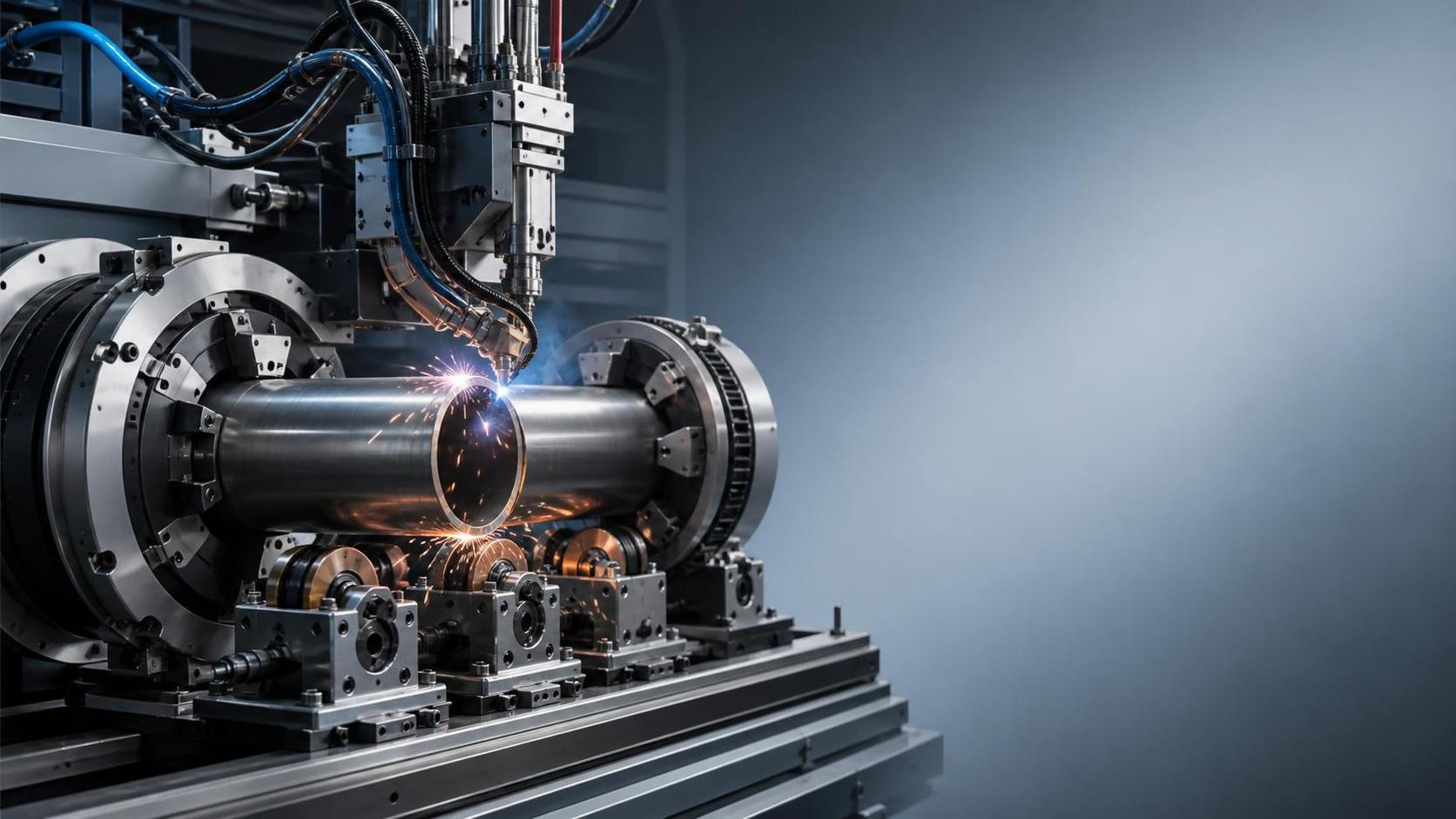
Throughput and fit-up accuracy have to be judged together
A Pipe Welding Station that produces fast cycle times but struggles to hold joint alignment will usually create hidden delays downstream. Rework, arc interruptions, tack correction, and extra inspection time can erase the apparent speed advantage of a high-output system. A better evaluation starts with the actual pipe range, wall thickness, joint design, and target weld process, then looks at whether the station can keep those variables stable over a full shift rather than only during a short demonstration.
For most pipe fabrication lines, throughput is not simply arc-on time. It includes loading, centering, clamping, edge condition consistency, root gap control, torch positioning, interpass handling, unloading, and the time required to correct mismatch. Fit-up accuracy is the condition that allows the welding cycle to run as programmed. If bevel faces are inconsistent, pipe ends are out of round, or the station cannot compensate for dimensional scatter, the nominal welding speed becomes less meaningful.
Start from the real workpiece window
Evaluation becomes distorted when a station is judged on a narrow sample that does not represent production. The pipe diameter range matters, but so do wall thickness transitions, material grade, straightness, ovality, bevel type, and cut-end quality. Carbon steel pipe with stable upstream preparation behaves differently from stainless pipe with stricter heat input limits, and both differ from heavy-wall alloy pipe where joint mass changes the thermal response.
The practical question is whether one station can maintain repeatable fit-up across the whole workpiece window or only near its ideal size. A machine that aligns pipe very well at one diameter may lose consistency when the chuck reaches the upper or lower end of its clamping range. The same issue appears when switching from standard butt joints to joints requiring controlled land, compound bevels, or tighter root face tolerances.
End preparation quality should be included in the review even if it comes from another machine. A Pipe Welding Station often inherits variation from cutting and beveling. If pipe ends arrive with burrs, local deformation, or angular inconsistency, the welding station may need extra compensation capacity. In some workshops, upstream plate preparation also affects pipe seam quality before rolling and welding. Where sheet or plate blanks are processed in-house, a stable cutting stage can reduce later fit-up correction; for example, a Hydraulic guillotine shear used for straight-line cutting of medium-thick plate may be relevant when consistent blank dimensions are required before rolling, especially if repeat positioning and shear accuracy are being closely controlled.
Read throughput as a sequence, not a single number
Quoted productivity figures often compress several assumptions into one headline number. For a useful comparison, separate the cycle into distinct segments and time each one under realistic conditions. Loading speed depends on pipe handling method, operator access, fixture opening stroke, and whether the station tolerates small positioning errors during insertion. Centering and clamping speed depend on how many axes move simultaneously and whether the control system needs manual confirmation before welding can start.
Once the pipe is clamped, actual welding throughput depends on travel speed, deposition requirements, seam tracking behavior, and whether the station pauses when gap or mismatch shifts out of range. A system with a moderate programmed welding speed may outproduce a nominally faster one if it restarts less often and needs fewer touch-ups between passes.
It is also worth separating first-part throughput from repeated throughput. Some stations perform well after setup has been optimized by a skilled technician, but their shift-to-shift repeatability is weaker. Recipe recall, automatic parameter adjustment, and guided setup screens can help, but only if the mechanical references return to the same position and the sensors remain stable after thermal growth, vibration, and contamination.
Fit-up accuracy is mostly mechanical before it becomes digital
Vision systems, seam tracking, and adaptive control can correct some variation, but they cannot fully compensate for a weak mechanical base. The core questions are simple: does the station position both pipe ends on the same axis, hold them there under clamping force, and keep the torch in the intended relationship to the joint during rotation or travel?
Mechanical rigidity should be examined at the chuck, support rollers, carriage, torch mount, and frame. Heavy-wall pipe and larger diameters amplify small deflections. If support spacing is inadequate, the pipe may sag enough to alter root alignment at the joint. If clamping force is poorly distributed, the station may deform thinner-wall pipe and create an artificial mismatch that disappears only after unclamping, which can mislead operators during inspection.
Backlash and servo tuning also matter. An axis that technically repeats position in a no-load test may behave differently under rotating mass, cable drag, or intermittent correction commands. The best assessment is to measure repeatability under production-like loading, not only from controller diagnostics. Indicators, laser measurement, or fixture-based gauges can reveal whether the machine returns to the same fit-up position after repeated clamp-release cycles.
Where mismatch really comes from
Many misjudgments happen because all dimensional error is blamed on the welding station. In practice, mismatch can come from several sources at once:
- Pipe ovality that changes the contact condition as the workpiece rotates.
- Inconsistent bevel geometry, including local land variation or non-uniform included angle.
- End squareness error from cutting or facing.
- Fixture wear, especially on jaws, rollers, and locator faces that see repeated metal contact.
- Thermal drift during long runs, where supports and torch stand shift slightly as the structure warms.
A worthwhile station evaluation reproduces those disturbances intentionally. If possible, include a sample with mild ovality, one with ordinary shop-floor bevel variation, and one heavy enough to challenge the support system. That usually shows more than a polished sample prepared specifically for acceptance testing.
Automation stability should be tested under interruption
A station can appear stable when it runs one uninterrupted weld from a cold start. Production conditions are rougher. There may be consumable changes, temporary arc faults, fixture opening and reclamping, and material surface variation from oil, scale, or spatter. Automation stability should therefore include restart behavior, fault recovery, sensor contamination tolerance, and the consistency of stored programs after repeated use.
Seam tracking deserves careful scrutiny. On paper, adaptive tracking sounds sufficient to absorb fit-up variation, but actual performance depends on sensor type, mounting stiffness, signal filtering, and how correction commands are blended into axis motion. Overactive correction can introduce oscillation, while sluggish correction may allow the torch to drift off the joint. In stations intended for multi-pass welding, check whether the tracking reference remains dependable after the first pass changes the joint profile.
Program storage is useful only if recipe management is disciplined. The system should make it clear which parameters belong to pipe diameter, wall thickness, material, welding position, and pass sequence. Ambiguous naming or scattered adjustment pages can create setup errors that are mistaken for mechanical inaccuracy.
Compatibility with upstream and downstream equipment
A Pipe Welding Station should be reviewed as part of a line, even when purchased as a standalone unit. Upstream processes often define whether the station can achieve both speed and joint accuracy. Pipe end facing, beveling, cleaning, and part identification all influence setup time. Downstream requirements such as radiographic inspection, hydrotest preparation, coating allowances, or assembly to flanges and fittings influence acceptable mismatch and reinforcement.
Interface details deserve more attention than they usually get. Roller conveyor height, datum transfer between stations, crane access, pipe support spacing, and software communication with part tracking systems can all affect flow. If the welding station has accurate internal positioning but receives poorly referenced workpieces from adjacent equipment, the line may still lose time in manual correction.
Power supply and utility conditions should also be reviewed without assumption. Voltage stability, shielding gas quality, compressed air dryness, hydraulic cleanliness, and cooling-water conditions can affect weld consistency and machine uptime. In some workshops, these peripheral issues cause more downtime than the welding head itself.
Look closely at the torch, wire, and heat path
Fit-up accuracy is inseparable from the welding process selected for the joint. GMAW, GTAW, SAW, or hybrid arrangements place different demands on torch access, groove tolerance, and travel stability. A station intended for root pass control on thin-wall stainless pipe needs a different level of torch positioning delicacy than one built for heavier carbon steel fill and cap passes. The evaluation should confirm that torch angle adjustment, contact tip access, wire feed path, and cable routing remain stable across the pipe size range.
Wire feed consistency is easy to overlook during mechanical review. Long cable packages, rotating heads, tight bends, or insufficient support for the wire conduit can cause small but recurring feed disturbances. Those disturbances may show up first as inconsistent bead appearance, then as throughput loss because operators reduce travel speed or stop to correct the process.
Heat management is another hidden variable. On thicker sections, repeated welds can warm fixtures, drive off lubricants, and alter sensor behavior. On thin-wall pipe, excess heat input may increase distortion and make the next station appear inaccurate when the issue is actually weld-induced deformation. A meaningful trial should therefore include consecutive production-like cycles rather than isolated welds with full cooling between samples.
Installation and transport details affect later accuracy
Large welding stations can lose alignment during transport, unloading, and installation if the base frame is not supported correctly. That is not a shipping complaint; it is an accuracy issue. The machine should be evaluated for leveling requirements, foundation sensitivity, anchor point design, and the ease of verifying geometry after installation. If field re-leveling is difficult, long-term fit-up consistency may depend too much on the original commissioning team.
For plants with limited space, loading direction and maintenance clearance should be checked with actual pipe length and turning radius in mind. A station that fits on a layout drawing may still create awkward pipe handling that extends cycle time or increases the chance of bumping sensors and torch mounts.
Maintenance intervals matter because wear changes the joint before failure stops the machine
A useful review does not stop at whether the station can be repaired. It should ask how wear shows up in production before an obvious breakdown. Jaw faces polish and lose grip characteristics. Rollers pick up debris. Slides accumulate fine metal particles. Hydraulic or pneumatic clamping components may still function while no longer holding exactly the same reference position. When those shifts are small, they tend to appear first as fit-up scatter rather than as alarms.
Inspection access is therefore important. If key wear points cannot be checked quickly, small accuracy losses may continue until weld rejection exposes the issue. Lubrication points, sensor cleaning access, calibration routines, and replacement of contact components should be straightforward enough to perform without dismantling unrelated assemblies.
Where the line also handles plate preparation, the same maintenance logic applies to supporting equipment. For instance, straightness and dimensional repeatability from a shearing stage can influence rolling and seam preparation quality later on. A machine such as the Hydraulic guillotine shear, with automatic rear stopper adjustment, multiple program storage, laser alignment, AI visual correction, and safety interlock protection, may be relevant where the fabrication route depends on consistent blank preparation for downstream pipe or shell forming.
Common evaluation mistakes
One common mistake is accepting a station demonstration with ideal samples only. Another is relying on static accuracy values without asking under what load, temperature, and clamping condition they were obtained. Repeatability figures are useful, but they should be tied to the actual axis, payload, and cycle pattern involved in pipe fit-up. A third mistake is focusing only on the welding head while ignoring the material preparation chain that feeds it.
It is also easy to overestimate the value of automation features when the joint condition remains unstable. Automatic adjustment and stored programs improve consistency when the mechanical and dimensional baseline is already controlled. They are less effective when upstream pipe ends vary beyond the correction window. In that case, a station may appear underperforming even though the real constraint lies in cutting, facing, or handling.
The strongest Pipe Welding Station evaluation usually comes from observing whether the machine maintains joint condition from the first clamp to the last pass with ordinary shop variation present. If that stability is there, the throughput figure means something. If it is not, the speed number is mostly a test-bay artifact.
search
Products Navigation
Send Us A Message