




Why Handling Robot Cells Lose Accuracy—and How to Restore Repeatable Placement
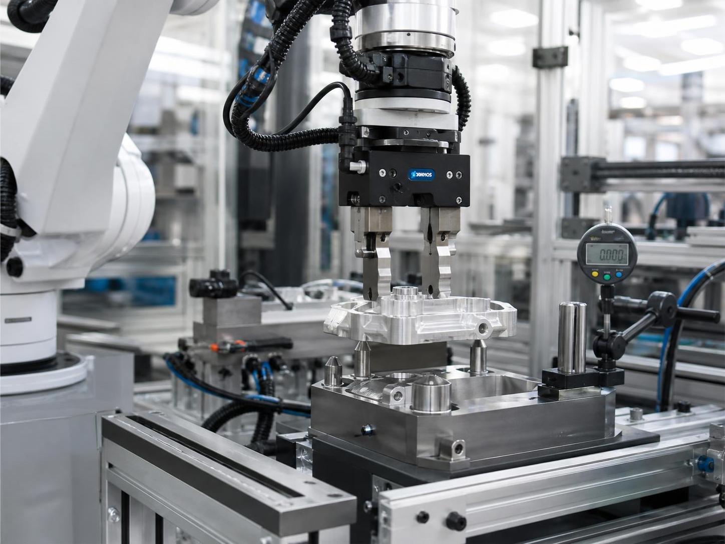
When a Handling Robot begins placing parts a few millimeters away from the expected location, the visible error is usually the last stage of a longer chain. A pallet may appear to have shifted, a gripper may seem to release late, or a taught point may look incorrect. Re-teaching the point can temporarily hide the symptom, but repeated placement will remain unstable when the underlying reference, mechanism, tooling, or motion condition has changed.
Start by separating repeatability from absolute accuracy. A robot that returns to the same wrong point cycle after cycle may still be mechanically repeatable; its base frame, user frame, tool center point, or fixture datum may be wrong. A robot that lands in a different place on each cycle has a different fault pattern. Variable errors point more often to backlash, loose hardware, payload changes, unstable workholding, servo behavior, cable interference, or variation in the incoming part.
Read the Error Pattern Before Changing Coordinates
A useful first observation is whether the offset is constant in direction and size. If every part is displaced 3 mm toward the cell door, inspect the relation between the robot base and the fixture. A moved fixture, altered user frame, incorrect pallet locator, or base movement can create this pattern. If the error grows as the wrist reaches farther from the robot, review tool data, payload, arm deflection, and the taught approach geometry.
When the miss changes after a direction reversal, look for lost motion. For example, a robot may approach a pin from the left and seat correctly, then approach the same pin from the right and stop short. That behavior can result from joint reducer wear, a loose flange connection, compliance in an end effector, or movement in a locating unit. It can also occur when a gripper contacts a part before the programmed stop point and bends the part or fixture slightly.
Time-dependent drift deserves separate attention. A cell may run acceptably after startup and lose placement quality after several hours. In that case, record ambient temperature, cabinet temperature, cycle rate, payload, and the point at which the deviation appears. Thermal expansion in a long fixture, warming gearboxes, reduced pneumatic pressure during peak demand, or heat from welding and cutting nearby can alter the physical condition around a Handling Robot. Correcting a hot-cell error by changing cold-cell coordinates creates another error when the cell cools.
Establish a Stable Measurement Reference
Do not diagnose placement against an unverified production part. Use a rigid master target, precision pin, gauge plate, or calibrated fixture feature that is independent of movable product nests. The target must be secured to the same structure being evaluated. If the concern is robot-to-fixture accuracy, place the target on the fixture. If the concern is robot mounting stability, use a target fixed to the floor or a verified cell datum.
Bring the robot to the target from several directions at a controlled low speed. Record the displayed position and the physical offset at each approach. The aim is to identify direction sensitivity, not simply to obtain one favorable reading. Repeat the test with the production gripper installed because a bare wrist test may miss compliance caused by finger flex, vacuum cup deflection, poor coupler seating, or a loose adapter plate.
Before changing calibration values, preserve the existing state. Back up programs, system variables, frame data, tool data, payload settings, mastering records, and any vision or PLC offsets. Mark the current physical datum where practical. This allows a controlled comparison after corrective work and avoids compounding an uncertain calibration with an unrecorded change.
Mechanical Sources Often Hide Behind Programming Symptoms
Inspect the robot mounting bolts, pedestal, floor anchors, welds, and any riser or side-mount bracket. A small movement at the base becomes larger at full reach. Look for witness marks around bolt washers, cracked grout, corrosion under the base, elongated mounting holes, and shims that have shifted. Verify tightening according to the applicable robot and mounting documentation; arbitrary torque values can damage threads or leave the joint unreliable.
The end-of-arm tooling deserves the same level of attention. Check the wrist flange fasteners, locating spigot, adapter plate, quick-change coupler, gripper body, finger mounts, and sensor brackets. A handling gripper can be tight when empty yet move under the moment created by a loaded part. Compare the observed error with the load orientation. If the placement error appears only when carrying a long tube, formed sheet, casting, or stacked blank, inspect for deflection and for contact between the payload and cell hardware during travel.
Gripper condition changes the effective tool center point. Bent fingers, worn locating pads, damaged vacuum cups, uneven jaw travel, and accumulated spatter can all move the part relative to the programmed TCP. For vacuum handling, compare cup compression at the pickup and placement surfaces. A cup that compresses differently against oily sheet metal, coated plate, or a slightly warped blank can alter the part position without any robot-axis fault.
Joint backlash should be evaluated carefully. Do not infer reducer failure merely because a dial indicator shows movement while the brakes are engaged; structural compliance and brake behavior can affect that reading. Use the robot manufacturer’s recommended inspection procedure, compare the affected axis across direction changes, and review alarms, axis load history, abnormal noise, heat, or grease leakage. Mechanical repair should be followed by mastering verification before production points are adjusted.
Frames, TCP Data, and Mastering Need a Defined Order
Calibration changes are most reliable when performed in sequence. First verify that the robot is mechanically sound and securely mounted. Then confirm mastering or encoder reference status. After that, establish the robot base frame, user frame, and tool center point. Only then should taught positions be corrected. Changing all of these at once removes the ability to identify which reference caused the shift.
A lost mastering condition may be obvious after battery failure, motor replacement, encoder work, or controller replacement, but partial errors can be less clear. A robot can still move smoothly and execute a program while its joint reference is offset. Compare known witness positions or mastering marks where the robot design permits. If an axis was serviced recently, verify whether the proper calibration procedure, fixture, and software step were completed rather than assuming the axis returned to its previous reference.
User-frame mistakes are common after fixture replacement or program transfer. A frame taught from three points will inherit error from each physical point and from the probe or tool used to touch them. Choose datum points that are rigid, accessible, and well separated. Avoid using a thin sheet edge, movable clamp, painted surface, or damaged locator as a calibration feature. On a pallet system, verify that the pallet is fully seated against all locators before teaching the frame.
TCP errors are especially visible during orientation changes. If a gripper picks correctly at one angle but misses a placement feature after wrist rotation, validate the TCP with multiple robot poses rather than a single-point touch. A fixed TCP should remain at the same physical target as the robot changes orientation. If it traces a circle or wanders, inspect both the mathematical TCP and the mechanical assembly that defines it.
Fixtures and Material Flow Can Move the Target
A robot can be accurate while the workpiece is not. Fixture movement may be caused by worn locating pins, insufficient clamp force, damaged stop blocks, loose nest plates, chips beneath a part, or a locating surface distorted by welding heat. Sheet metal handling adds further variation: a blank may spring after release, sag under its own weight, or arrive with burrs that prevent complete seating. Tubes and profiles can rotate against a simple V-block unless a positive angular locator is present.
Examine the placement sequence as a physical event. A high-speed approach followed by abrupt deceleration can push a light fixture or cause a thin part to slide before clamps close. A robot should normally approach the final placement region with a defined speed, orientation, and clearance path. Where contact is intended, use a controlled compliant motion strategy only when the equipment and process support it. Forcing a part into an uncertain feature can conceal a datum fault while damaging pins, fingers, or the part edge.
Part presentation upstream also matters. Conveyor stops, escapements, lift tables, centering devices, and pallet transfers must return to a repeatable mechanical position. A photoelectric sensor may confirm that a pallet is present without confirming that it is seated. Review interlocks for clamp-closed, lift-at-height, pallet-latched, and locator-extended signals. A permissive based only on elapsed time can allow the robot to move before the mechanism settles.
Control and Motion Conditions That Disturb Placement
Review the actual payload model, including gripper mass, part mass, center of gravity, and inertia. A payload value based on an empty gripper can produce poor path behavior with a heavy workpiece, particularly near wrist limits or during rapid direction changes. Conversely, an overstated payload can make motion unnecessarily conservative. Use measured or documented values where available, and include hoses, cable dress packs, adapters, and interchangeable fingers that move with the wrist.
Inspect external cables and pneumatic lines throughout the full path. A dress pack may pull on the wrist only near one joint combination, creating an intermittent offset that resembles a servo issue. Look for snagging, tight bend radii, abrasion, collision marks, and hoses that contact guards or fixtures. Changes made after installation, such as a new air line or sensor cable, should be treated as possible contributors.
In cells with vision guidance, distinguish camera calibration error from robot error. Confirm camera mounting rigidity, lens cleanliness, illumination stability, target contrast, and the transformation between camera coordinates and robot coordinates. Recalibrate only against a verified physical datum. A camera may report a plausible correction even when the reference target has moved, leading the robot to compensate in the wrong direction.
For applications requiring a 6-axis robot with a 20 kg wrist payload, a 2102 mm maximum reach, and stated repeatability of +/-0.08 mm, the installed cell still determines the achieved placement result. The Multipurpose Handing Robot BR20iB-20 can be ground mounted, hoisted, or side mounted, so the stiffness and datum control of the selected mounting structure need to match the required path and payload conditions. Flexible installation changes the mechanical load path; it does not remove the need to validate the base frame after installation.
Recover Production Without Creating a Hidden Offset
After repairs or corrections, validate the cell at more than one position. Test a central point and points near the working envelope boundaries, with the normal gripper and representative payload. Run repeated approach cycles from the same direction, then introduce the directions used by the production program. Observe pickup seating, travel clearance, final placement, release behavior, and withdrawal. A correction that works only at one station may indicate an unresolved frame, TCP, or structural issue.
Restore normal speed gradually. Slow-speed validation confirms geometry, while production-speed validation exposes deflection, settling time, braking effects, and cable interference. Monitor the first production cycles closely for contact marks, shifted parts, clamp interference, unusual axis load, and pneumatic instability. When a position is changed, record the reason, measured condition, frame or tool data affected, and the test result. This history makes later drift easier to distinguish from a past correction.
Repeatable placement is preserved by treating the robot, tooling, fixture, part presentation, and controller references as one positioning system. Coordinates should be the final adjustment, made after the physical system has been measured and stabilized. That approach prevents a short-term program edit from becoming a recurring source of rejects and unplanned cell intervention.
search
Products Navigation
Send Us A Message