




How Teach-Free Intelligent Welding Robots Generate Paths Without Manual Programming
How Teach-Free Intelligent Welding Robots Generate Paths Without Manual Programming
For a technical evaluator, the appeal of a Teach-free Intelligent Welding Robot is not simply that it welds automatically. Conventional robotic welding has been automated for decades; the difficult part has often been creating and maintaining the robot program. When a fixture changes, a workpiece shifts, a seam varies, or a new component reaches the line, an experienced programmer may need to re-teach points, adjust torch angles, verify clearances, and run trial parts.
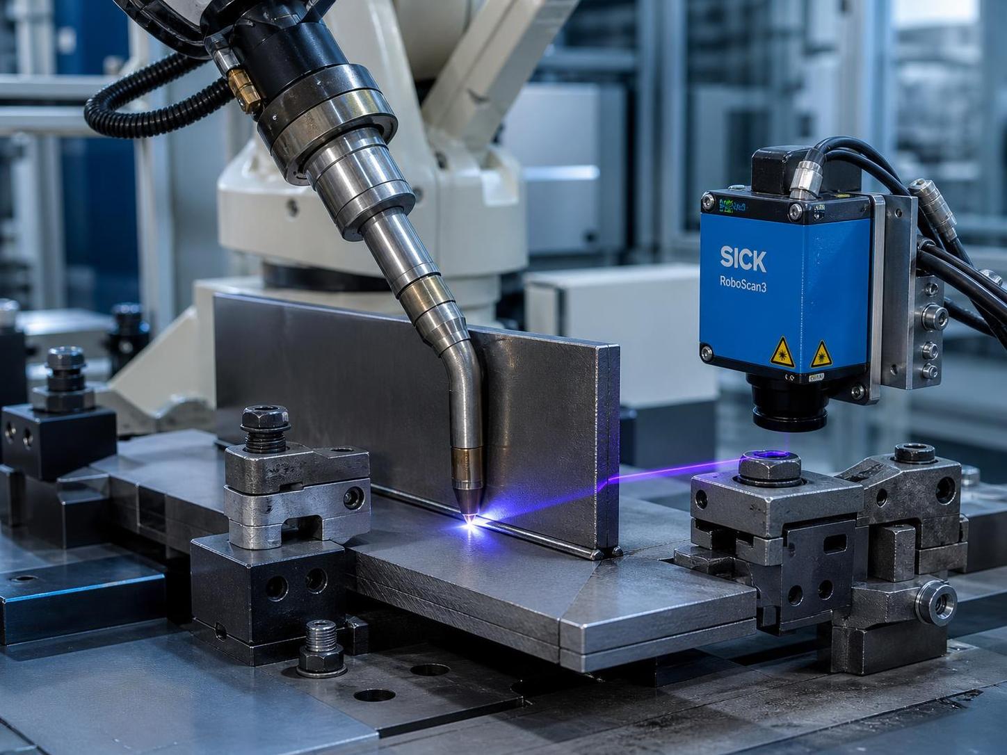
Teach-free systems change that workflow. Rather than depending on a manually recorded sequence of robot positions, they use sensing, geometric interpretation, path planning, and closed-loop control to derive a welding trajectory from the actual workpiece. The robot is not “guessing” where to weld. It is building a usable coordinate model from measured features, then converting that model into motions and welding parameters that can be validated before the arc is started.
This distinction matters most in high-mix fabrication, structural steel, machine frames, pressure-related assemblies, and other environments where part variation is normal rather than exceptional. The technology can shorten setup time and reduce reliance on repeated manual teaching, but its real value depends on how reliably each stage—from seam detection to final process control—has been engineered.
The Shift from Taught Points to Measured Geometry
A traditional welding robot typically follows a path created through pendant teaching or offline programming. The path is based on a nominal CAD model, a fixed fixture, or an operator’s recorded positions. This can be effective for stable, high-volume products. Yet it is sensitive to variation: a few millimeters of part displacement, a change in joint preparation, thermal distortion, or a replacement fixture can make an otherwise valid program unsuitable.
A teach-free approach begins with the physical part in front of the robot. Depending on the system architecture, it may use laser profile sensors, 2D or 3D cameras, structured light, stereo vision, tactile probing, or a combination of these methods. The objective is to establish three things:
- Where the workpiece is located in the robot cell;
- Which features define the weld joint; and
- What path, torch orientation, and travel conditions are needed to execute the weld.
In practical terms, the robot does not need every surface of the component to be perfectly reconstructed. It needs a sufficiently accurate representation of the welding-relevant geometry: seam centerline, start and end points, local joint orientation, accessible approach direction, and boundaries where welding must stop. For a fillet weld on a fabricated bracket, for example, the intersection of two plates may be enough. For a complex tubular assembly, multiple scans may be required to resolve the joint around changing contours.
What Actually Happens Before the Robot Strikes an Arc
The phrase “no programming” can be misleading if it suggests that no engineering preparation is needed. Teach-free welding replaces repetitive point-by-point programming with a more automated planning process. The core workflow is usually composed of the following technical steps.
1. Workpiece localization
The cell first determines the part’s position and orientation relative to the robot base. This may be done by recognizing reference holes, edges, corners, fiducial marks, fixture features, or known geometric patterns. If the actual part is rotated or shifted relative to its nominal location, the coordinate transformation updates the planned weld accordingly.
Localization quality is fundamental. A sophisticated seam-tracking function cannot fully compensate for a poor initial coordinate relationship, especially when the robot must avoid clamps, approach a narrow groove, or maintain a specific torch angle. Evaluators should therefore examine how the system establishes its work object coordinate system and how it flags uncertain recognition results.
2. Seam recognition and joint classification
Once the component is located, the sensor scans candidate welding regions. Image-processing or profile-analysis algorithms identify geometric signatures such as V-grooves, lap joints, butt joints, T-joints, corner joints, and fillet joints. The result is more than a visible line. A useful seam model includes the center or target track, local surface normals, groove width or depth where applicable, and changes in seam direction.
Recognition algorithms need to distinguish a true joint from edges, scratches, tack welds, spatter, mill scale, reflected light, and nearby structural features. This is where laboratory demonstrations and production performance may diverge. Bright aluminum surfaces, dark oxidized steel, irregular galvanizing, and heavy fit-up variation all place different demands on sensing hardware and algorithm robustness.
3. Path generation in Cartesian space
After the seam is identified, the controller creates a path in Cartesian coordinates. It defines the weld start point, end point, travel direction, intermediate points or curves, approach motion, retreat motion, and torch pose along the seam. For curved or multi-segment joints, the generated path is commonly smoothed to avoid abrupt robot motion and unstable travel speed.
The torch pose is as important as the centerline. A welding path must account for work angle, travel angle, contact-tip-to-work distance, wire extension, and the preferred direction of travel. On a fillet joint, a small change in torch orientation can shift heat distribution between the two members. A path that looks correct in a 3D viewer may still be metallurgically or operationally poor if the process orientation is wrong.
4. Collision and reachability checks
Before execution, the robot controller or offline planning environment checks whether the robot can reach the path without exceeding joint limits, entering singular configurations, or colliding with fixtures, positioners, clamps, cables, sensors, or the workpiece itself. This step becomes particularly important with long H-beams, deep box sections, and assemblies that require multiple welding orientations.
A system should be able to report when a seam is recognized but cannot be reached safely. Silent failure is unacceptable; technical teams need clear diagnostic information that separates sensing errors, kinematic limitations, and collision constraints.
5. Conversion into robot and welding instructions
The planned trajectory is then converted into robot motion commands and welding process instructions. These can include speed, arc start and stop timing, weaving pattern, wire feed settings, voltage targets, gas flow requirements, crater fill behavior, and position-dependent parameter changes. In more advanced cells, the system selects a process recipe based on joint type, material thickness, welding position, and seam geometry.
At this point, the generated path becomes an executable program, even though an operator did not manually teach each point. The distinction is important for traceability: a well-designed cell should store the detected seam data, selected recipe, planned path, actual execution record, and any operator interventions.
Adaptive Control Continues During Welding
Pre-weld vision provides the initial path. It does not eliminate the need for in-process adaptation. Heat can distort a component after the first pass, gaps can change along a seam, and fit-up may differ from one end of a structure to the other. To address this, many intelligent welding cells combine pre-scan data with real-time seam tracking.
Laser seam tracking can measure joint position ahead of the weld pool and apply path corrections while welding. Through-arc sensing may infer changes in torch-to-work distance from electrical signals. Depending on the process, the controller can adapt lateral position, height, travel speed, weaving width, or other selected variables within validated limits.
It is useful to separate path correction from quality assurance. Tracking keeps the torch near the intended seam. It does not by itself prove penetration, fusion quality, or absence of internal defects. A serious evaluation plan should consider whether the application also requires bead inspection, visual inspection systems, destructive qualification testing, NDT, or process monitoring consistent with the applicable welding procedure requirements.
Why Upstream Cutting Accuracy Still Influences “Intelligent” Welding
Teach-free welding is often selected because fabricators expect it to absorb variation. It can absorb some variation, but it should not be treated as a substitute for controlled upstream fabrication. Excessive gap variation, rough cut edges, inconsistent bevel geometry, and severe distortion limit what any seam-recognition and adaptive welding system can correct.
For structural components and beam-based fabrication, cutting quality has a direct effect on joint fit-up and on the repeatability of recognition. A CNC preparation process such as an H beam cnc fiber laser cutting machine can support more consistent geometry before parts enter welding. Laser cutting is non-contact and suitable for complex CNC-defined profiles; its narrow kerf and controlled edge quality can help reduce the uncertainty that downstream sensing must interpret. The relevant question is not whether laser cutting and intelligent welding are separate investments, but whether their dimensional and data workflows are aligned.
Where CAD/CAM data is available, part identification, cut features, and expected weld locations can also provide useful context to the welding cell. Vision should verify the physical reality of the part, while design data can constrain the search area and improve planning efficiency. The strongest implementations use both rather than relying blindly on either one.
How Technical Evaluators Should Test a Teach-Free Intelligent Welding Robot
Vendor demonstrations often show a clean workpiece placed in a known position. That is a valid starting point, but not a sufficient acceptance condition. Evaluation should reflect the production conditions that create the need for teach-free operation in the first place.
- Part-position tolerance: Test deliberate shifts and rotations within the expected loading range. Verify whether the robot re-localizes the workpiece and whether the generated path remains within the required welding tolerance.
- Joint variation: Include realistic gaps, tack welds, bevel inconsistencies, surface scale, and minor distortion. Document the range the system recognizes successfully and the conditions that trigger a reject or manual review.
- Surface and lighting conditions: Assess reflective materials, dark surfaces, contaminants, and workshop lighting. Sensors that perform well on matte coupons may need different exposure strategies on production parts.
- Cycle-time accounting: Measure scan time, computation time, robot repositioning, welding time, and any required operator confirmation. “Programming-free” does not automatically mean the shortest total cycle.
- Recovery behavior: Interrupt a cycle, introduce a failed scan, or present an out-of-tolerance part. Determine whether the system provides clear recovery procedures and preserves traceable records.
- Weld-quality validation: Qualify the resulting procedure through the inspection and testing methods appropriate to the product standard, material, and service conditions.
The acceptance criteria should be written before the evaluation begins. They may include seam-finding success rate, path deviation, weld bead placement, repeatability after part replacement, permitted setup duration, and documented handling of nonconforming parts. Without such criteria, teams can be impressed by automation while missing the conditions that matter on their own shop floor.
Standards, Safety, and Process Boundaries
A teach-free system remains an industrial robot welding cell and must be assessed accordingly. Robot safety, safeguarding, emergency stops, interlocks, risk assessment, fume extraction, electrical safety, laser-sensor safety where relevant, and welding power-source integration all require attention. Depending on the market and installation, applicable requirements may include ISO 10218 for industrial robot safety, ISO 13849 or IEC 62061 for safety-related control functions, and ISO 14732 for welding personnel responsibilities. Product-specific welding quality requirements may also point to ISO 3834, ISO 5817, AWS codes, or customer-defined specifications.
Compliance is not achieved by attaching a standard number to a quotation. Evaluators should request the cell’s risk-assessment boundaries, safety architecture, declared operating modes, validation documents, and clarity on who is responsible for final integration. This is especially important where a robot cell is combined with external axes, turning rolls, beam conveyors, or custom fixtures.
A Practical Decision: Where Teach-Free Technology Fits Best
A Teach-free Intelligent Welding Robot is usually most compelling when manual programming has become a bottleneck: frequent product changes, low-to-medium batch sizes, variable loading positions, lengthy seams, large structures, or limited availability of experienced robot programmers. It can also be valuable where repeatable weld placement is difficult for operators to sustain across long shifts.
Conversely, a simple fixed product with stable dedicated tooling may not need the full complexity of vision-guided path generation. A conventional robot program can remain the more economical option when part geometry, fixture position, and production volume rarely change.
The right evaluation question is therefore not, “Can the robot generate a path?” Most modern systems can demonstrate that capability. The better question is: “Can it generate, validate, execute, and document the right path under our actual part variation, quality rules, and production rhythm?” When the answer is supported by realistic trials and sound integration engineering, teach-free welding becomes a practical manufacturing tool rather than a promising demonstration.
search
Products Navigation
Send Us A Message