




Which Joint Types and Part Variations Fit Teach-Free Intelligent Welding Robots?
Which Joint Types and Part Variations Fit Teach-Free Intelligent Welding Robots?
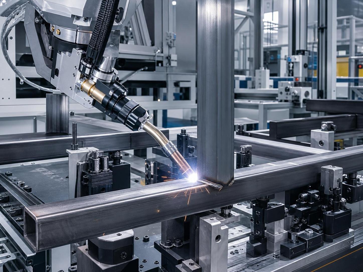
Selecting a welding robot is rarely just a question of payload, reach, or welding process. In real fabrication projects, the more decisive question is whether the robot can repeatedly find, interpret, and weld the joint condition presented by actual parts—not the ideal CAD model. That is where a Teach-free Intelligent Welding Robot can be useful. By combining seam sensing, adaptive path generation, and automated parameter adjustment, it can reduce the amount of manual point teaching required when part position or joint geometry changes.
For project managers, this is especially relevant in mixed production environments. A line may handle several frame sizes in one week, then switch to brackets, tanks, structural members, or pipe-related assemblies in the next. Traditional robotic cells can still perform well in these conditions, but repeated fixture changes and manual path correction often consume more time than expected. Teach-free systems are most practical where variation is controlled rather than random: the robot needs identifiable joint features, workable access, and a stable enough process window to make intelligent recognition meaningful.
The technology does not remove the need for welding engineering. It changes where the engineering effort is spent. Instead of teaching every point by hand, the team focuses more on joint preparation, datum selection, fixture strategy, sensing reliability, torch access, and acceptable variation limits. That is a better trade in many fabrication projects, but only when the joint family is suitable.
The Best Starting Point: Repeatable Butt and Fillet Welds
Butt joints and fillet joints are generally the most approachable applications for teach-free robotic welding. They provide recognizable edges, relatively predictable torch angles, and clear seam trajectories. That does not mean every butt or fillet weld is easy. A clean square butt joint on plate is very different from a narrow-gap joint with inconsistent root opening, and a simple T-joint is much more forgiving than a deep structural connection surrounded by stiffeners.
For butt joints, the strongest candidates are straight or gently curved seams on plate, profiles, shells, and fabricated sections where the workpiece can be located consistently. If the system uses laser vision or another seam-tracking method, it may identify the groove or edge position before welding and compensate for modest placement deviation. This is valuable when operators load parts manually and cannot achieve the same position every cycle.
However, project teams should separate two issues that are often mixed together: part location error and joint-fit-up error. A robot can often compensate for a part sitting several millimetres away from its nominal fixture position if the seam is visible. It cannot automatically solve poor fit-up, heavy mismatch, contamination, or a root gap outside the qualified welding procedure. Sensing tells the system what it sees; it does not make an unsuitable joint preparation acceptable.
Fillet welds on T-joints, lap joints, and angle frames are commonly good candidates because the intersection of two surfaces creates a distinct seam feature. Typical applications include machine bases, equipment frames, brackets, skids, support structures, and fabricated enclosures. These parts often vary in overall dimensions while keeping similar joint logic. A Teach-free Intelligent Welding Robot can be particularly useful when the robot must locate multiple fillets on a family of related parts instead of following one fixed program.
Where Fillet Joints Become Less Straightforward
The difficulty rises when the fillet is partially hidden, heavily tack-welded, or interrupted by tabs and gussets. Tacks can be necessary, but their size and placement matter. An oversized tack at the seam start may interfere with vision recognition or cause a robotic weld start to become unstable. Likewise, a joint with frequent gaps, uneven edge condition, or changing leg dimensions can require more than seam finding. It may need adaptive welding parameters, a revised fit-up process, or a different joint design.
A practical rule is to inspect the joint from the torch’s perspective, not only from the fitter’s perspective. If the robot cannot physically approach the seam at the required work angle and travel angle, accurate seam detection has limited value. This is easy to overlook on dense fabrications where human welders can change body position freely but the robot must work within a defined envelope.
Lap, Corner, and Edge Joints: Suitable, but Fixture Decisions Matter More
Lap joints are often a strong fit for automated welding when overlap is consistent and the exposed edge remains visible. They are widely found in sheet metal assemblies, covers, brackets, vehicle-related components, and fabricated boxes. The key concern is not simply whether the robot can see the edge. It is whether overlap variation changes the effective heat sink or risks burn-through. Thin material, coatings, and inconsistent clamping can make a visually simple lap seam difficult to weld consistently.
Corner joints can also work well, especially on box sections, cabinets, tanks, and welded frames. External corners are usually easier than internal corners because torch access and sensor visibility are better. Internal corner welds require careful checking for collisions between the torch body, nozzle, workpiece, and fixture. A robot may find the seam accurately but still lack enough clearance to maintain the desired torch orientation around the full contour.
This is one reason fixture design should not be treated as a secondary detail. Teach-free technology can reduce fixture precision requirements in some applications, but it does not mean fixtures become unnecessary. Good fixtures still control deformation, establish reliable datums, expose the weld area, and prevent parts from moving during the cycle. In practice, a simpler but well-thought-out fixture is often better than a complex fixture that obstructs the sensor or limits robotic access.
Part Variations That Usually Work—and Those That Need Caution
The right kind of variation is dimensional variation within a known part family. For example, a manufacturer may produce welded rectangular frames with different lengths and widths but the same tube section, corner configuration, and welding sequence. A teach-free cell may scan the frame, identify the joint positions, and create or adjust the path without requiring a separate fully taught program for every size.
Likewise, fabricated brackets with different hole layouts or flange lengths may remain suitable if the joints themselves are visible and structurally similar. The robot does not need every surrounding feature to be identical; it needs enough consistent geometric information to identify the intended weld and safely plan the approach.
Variation becomes risky when it changes the welding problem itself. Switching from carbon steel to stainless steel, changing thickness substantially, moving from open fillets to narrow grooves, or introducing different coating conditions may require a different welding procedure and consumable strategy. The robot may locate all of these seams, but process quality still depends on parameters such as current, voltage, wire feed, shielding gas, travel speed, interpass control, and heat input.
Circular and Longitudinal Pipe Seams Need a Different Decision
Pipe fabrication deserves separate consideration because the best automation architecture is not always a six-axis robot. Circumferential welds on fittings, flanges, and smaller assemblies can be suitable for robotic cells, particularly when workpiece rotation is available and the seam remains accessible. Longitudinal seams on rolled pipe, however, are often more efficient on dedicated seam-welding equipment when production is repetitive.
For batch production of carbon steel or stainless steel pipe, a dedicated solution such as the 12 meter Pipe inside and outside seam welding machine may be the more direct choice where the work falls within its intended range: pipe lengths up to 12 m, diameters from 400 to 1500 mm, and thicknesses from 6 to 20 mm. Its stated welding speed range is 0.4 to 1.2 m/min, with VFD-controlled trolley movement and video monitoring for the internal longitudinal seam process. SAW or MIG welding can be selected depending on the application.
This does not make intelligent robots irrelevant to pipe projects. It simply reflects a sensible division of labor. A dedicated machine is usually preferable when there is a stable, high-repeat longitudinal-seam workload. A robot becomes more attractive when the project includes different pipe attachments, supports, branch connections, reinforcing components, or mixed fabricated assemblies that cannot be handled efficiently by one dedicated travel system.
What Should Be Verified Before the Project Is Approved?
The fastest way to make a poor automation decision is to evaluate the robot using only a clean sample part. A proper feasibility review should include production parts representing normal variation: parts from different shifts, different material batches, and different fixture conditions. If distortion develops after tack welding, that state should be evaluated too. The robot has to succeed with the parts that actually arrive at the cell.
Before finalizing a solution, project teams should confirm the following:
- Whether every intended seam is visible to the sensing system before welding begins.
- Whether the torch can maintain suitable angles without collision across the entire seam.
- Which dimensional deviations the system is expected to compensate for, and which must remain controlled upstream.
- Whether the welding procedure is valid for each material, thickness, joint preparation, and welding position involved.
- How parts will be loaded, clamped, identified, and released without creating a new bottleneck around the robot.
- What inspection method will confirm that automated output remains within the required quality level.
It is also worth involving welding personnel early. Programmers and automation engineers may focus on reach and cycle time, while experienced welders will quickly notice where fit-up, distortion, starts and stops, or joint cleanliness could cause trouble. A successful cell normally combines both perspectives.
Choosing the Right Scope for Intelligent Welding Automation
The most suitable applications for a Teach-free Intelligent Welding Robot are not necessarily the most complex parts in the factory. They are the parts with repeatable weld intent, understandable geometric variation, accessible seams, and enough production frequency to justify automation. Straight and curved butt joints, visible fillet welds, lap seams, external corners, and repeatable frame or bracket families often offer a realistic starting point.
Wuxi Samgins International Trade Co., Ltd., established in 2012 in Wuxi, Jiangsu Province, works across automatic welding equipment, CNC cutting machinery, machine tools, H-beam production equipment, and sheet-metal processing machinery. That broader equipment perspective matters when planning a welding project: robotic welding performance is influenced by upstream cutting accuracy, edge preparation, forming quality, and material handling—not just by the robot itself. Production and design are organized in accordance with ISO9001 quality system requirements and EU CE standards, while final equipment selection should still be matched to the specific workpiece, process route, and applicable local requirements.
If the joint is hard to see, hard to reach, or fundamentally inconsistent, solve that manufacturing condition before expecting intelligent automation to compensate for it. When the joint family is well chosen, teach-free welding can reduce programming burden and make mixed fabrication work far more manageable. The first step is not selecting a robot model. It is mapping the real joints, the real variation, and the real constraints on the shop floor.
search
Products Navigation
Send Us A Message