




Automated Welding Cell: Design Checklist for Integrating Vision Guidance, Seam Tracking, and Real-Time Parameter Adjustment in Heavy Plate Fabrication
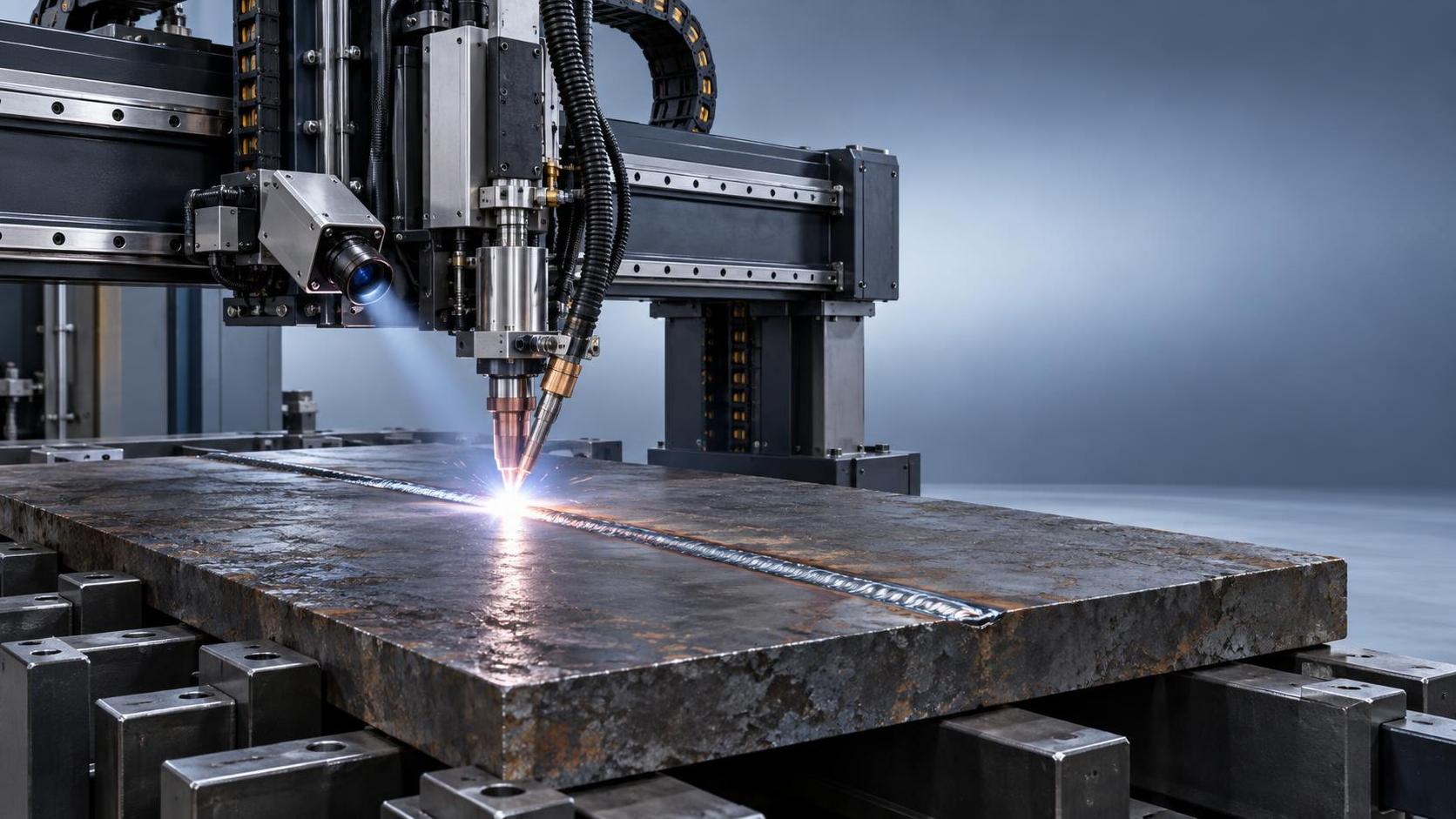
Designing an automated welding cell for heavy plate fabrication isn’t about assembling components—it’s about engineering a synchronized system where vision, tracking, and control respond to real-world variability in real time. For project managers overseeing structural steel projects—H-beam production lines, pressure vessel shells, or shipyard hull sections—the failure to integrate these three functions cohesively results not in minor delays, but in costly rework, dimensional drift, and compromised joint integrity. A misaligned seam tracker may miss a 0.3 mm gap variation; unadjusted parameters during heat buildup can cause root porosity in 25 mm plate; poor vision calibration leads to torch standoff errors that accumulate over 12-meter welds. These aren’t theoretical risks—they’re repeatable failures observed across fabrication shops where integration was treated as installation rather than orchestration.
The core issue isn’t hardware capability—it’s interface fidelity. Vision guidance must feed data to the seam tracker without latency; the tracker must trigger parameter shifts before thermal distortion propagates; and those adjustments must be executed with mechanical repeatability across shifts and operators. This checklist focuses on the six non-negotiable integration checkpoints—each grounded in field-deployed requirements for thick-plate applications—and maps them to functional verification points, not just specification sheets.
1. Vision Guidance: From Image Capture to Actionable Offset
Many assume high-resolution cameras guarantee accurate seam detection. They don’t—especially on mill-scaled, rust-prone, or thermally warped heavy plates. What matters is the closed-loop latency between image acquisition and coordinate correction. Verify that the vision system outputs positional offsets (X/Y/Z/rotation) directly to the motion controller—not via intermediate software layers or manual input. Confirm the system tolerates surface emissivity shifts: if welding transitions from preheated carbon steel to post-weld cooling zones, does contrast normalization adapt within 80 ms? If your process includes joint fit-up variations exceeding ±0.5 mm, ensure sub-pixel edge detection is validated against physical gauge blocks—not synthetic test patterns.
2. Seam Tracking: Real-Time Correction vs. Reactive Compensation
True seam tracking adjusts torch position *during* travel—not after arc ignition or between passes. Check whether the tracking sensor (laser triangulation or structured light) mounts rigidly to the welding head—not the gantry—so movement isn’t filtered out by frame flexure. Validate response time: under controlled lateral deviation (e.g., 1 mm step input), does the system correct within ≤150 ms at 0.8 m/min travel speed? Also confirm mechanical bandwidth: if the tracking signal demands >12 Hz servo updates, verify the motor-gear-rack assembly (like that used in the Longitudinal seam welding machine) sustains torque ripple below ±3% across its full speed range. Excessive ripple causes micro-oscillation in the weld bead—visible in macroetch tests as inconsistent fusion line geometry.
3. Parameter Adjustment: Context-Aware, Not Time-Based
Adjusting voltage or wire feed based on elapsed time ignores actual thermal mass changes. Effective real-time adjustment correlates parameter shifts to measured variables: arc voltage variance >±2 V over 3 seconds, IR surface temperature rise >15°C above ambient, or seam width deviation >±0.4 mm from nominal. Ensure your PLC logic allows conditional overrides—e.g., reduce travel speed by 15% *only if* both seam width widens *and* voltage drops simultaneously—rather than sequential timers. The Longitudinal seam welding machine’s PLC-controlled DC motor drive supports such stepless, condition-triggered regulation, critical when welding multi-pass joints in 40 mm plate where interpass temperature directly governs HAZ hardness.
4. Mechanical Synchronization: Clamping, Alignment, and Thermal Management
No amount of intelligent control compensates for mechanical instability. Inspect clamping force distribution: pneumatic key-type devices must apply uniform pressure across the entire workpiece length—not just at ends—to prevent bowing during weld thermal expansion. Confirm that spacing between pressing fingers and the welding core shaft is adjustable per workpiece diameter (e.g., 160 mm vs. 750 mm), as specified in ZF-2000 and ZF-3000 models. Verify thermal management: copper templates embedded in the core shaft must provide back-side gas shielding *and* conduct heat away from the weld zone—otherwise, localized annealing occurs beneath the seam, reducing yield strength in adjacent base metal.
5. Data Handshake Integrity: No “Black Box” Interfaces
If vision data flows through a proprietary SDK into a separate seam tracker module, then into a third-party PLC, latency and quantization errors multiply. Require native protocol support: EtherCAT or PROFINET for deterministic cycle times <1 ms; avoid USB or Ethernet/IP for motion-critical signals. Validate timestamp synchronization across all subsystems—vision, tracker, power source, and motion controller—using PTP (Precision Time Protocol). Without synchronized timestamps, a 5 ms delay in one subsystem appears as a 12 mm positional error at 2.4 m/min travel speed.
6. Validation Protocol: Test Beyond the First Pass
Most validation stops after successful first-pass welding on a clean test plate. That’s insufficient. Run a three-stage stress test: (1) Weld 3 meters on mill-scale plate with 0.8 mm gap variation every 500 mm; (2) Repeat with interpass cooling interrupted to simulate operator delay; (3) Perform final pass with 5% reduction in shielding gas flow to verify arc stability under marginal conditions. Measure outcomes—not just bead appearance—but root penetration consistency (via ultrasonic testing), angular distortion (±0.15° tolerance), and post-weld straightness (≤1.5 mm deviation over 3 meters). Only systems passing all three stages reliably support production-grade heavy plate fabrication.
Integration isn’t finalized when cables are plugged in—it’s confirmed when the system maintains weld quality across material batches, operator shifts, and ambient temperature swings. Each checkpoint here addresses a failure mode documented in actual deployment scenarios—not hypothetical edge cases. When evaluating an automated welding cell, treat integration not as a feature list, but as a chain: break any link, and the entire system degrades to manual oversight levels. For project managers, this means verifying not what each component *can do*, but how tightly they *must* operate together to hold dimensional and metallurgical tolerances in thick-section welding.
search
Products Navigation
Send Us A Message