




Can a rail mounted welding robot cover multiple welding stations?
The Real Question Is Capacity, Not Reach
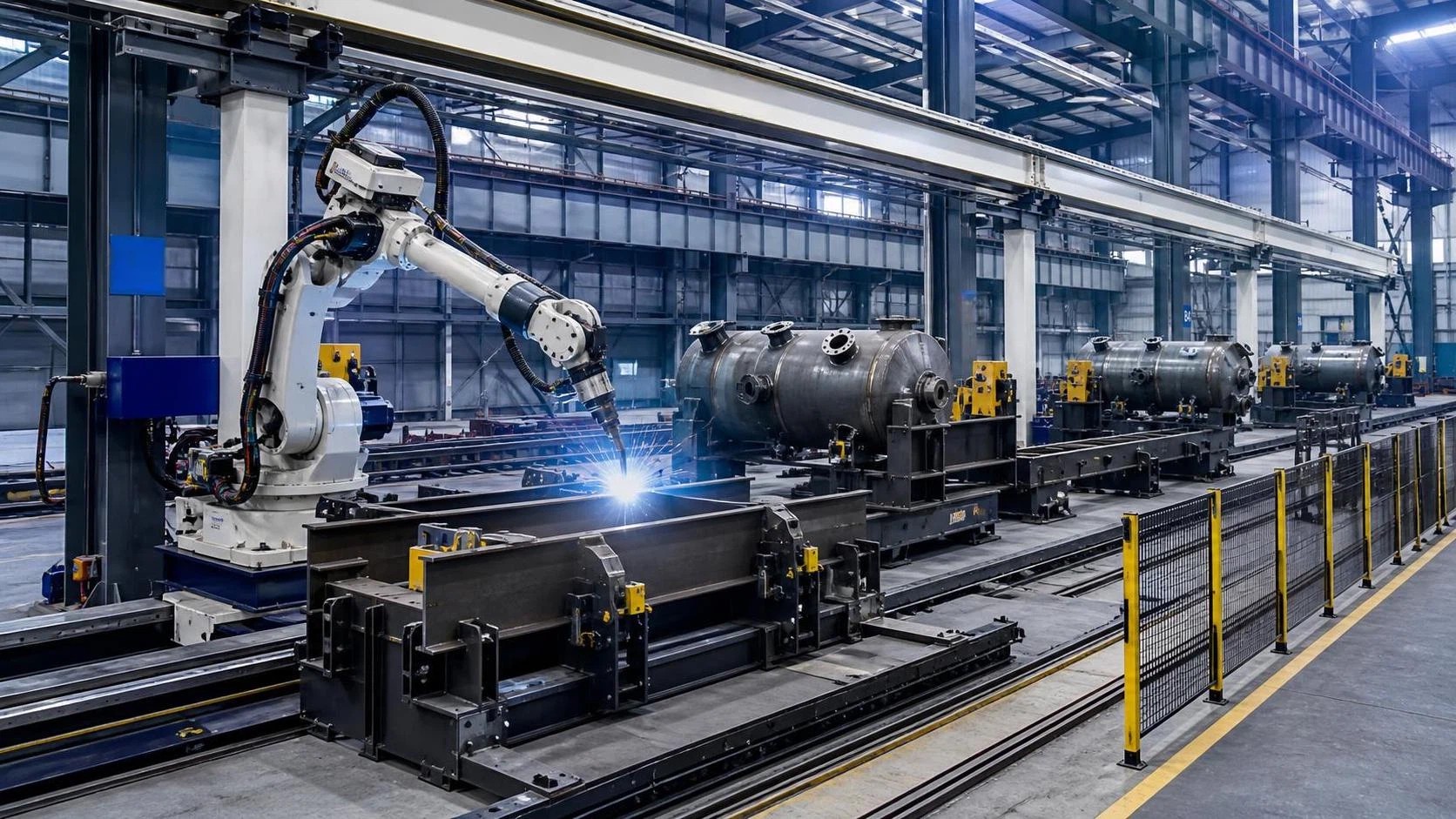
A rail-mounted welding robot can cover multiple welding stations, but only when the production flow is designed around the robot's travel time, station readiness, and quality-control requirements. For project managers, this is the central distinction. A robot that can physically move along a rail is not automatically a multi-station solution that improves throughput.
In high-volume fabrication of structural steel, pressure vessels, tank sections, pipe assemblies, frames, and heavy machinery components, a rail system can allow one robot or a coordinated robot group to serve workstations distributed along a long production line. That can reduce duplicated robot cells, make better use of floor space, and provide flexibility when product mix changes. It can also create a highly visible bottleneck if loading, fit-up, programming, or rail movement is not properly accounted for.
The practical question is therefore not simply, “Can one robot weld several stations?” It is: “Can the robot arrive at each station when the joint is ready, complete the required weld within the available takt time, and do so without creating unacceptable queueing, quality variation, or safety risk?”
Where Rail-Based Coverage Makes Sense
A rail-mounted welding robot is most useful where workpieces are large, stations are arranged in a reasonably linear pattern, and welding demand varies from station to station. Typical examples include long-beam fabrication, wind-tower components, tank shell sections, vessel fabrication, heavy structural members, ship blocks, and modular assemblies.
It is particularly attractive when a fixed robot cell would spend substantial time waiting for material handling, fixturing, tack welding, inspection, or crane access. Instead of assigning one robot to each intermittently active station, a rail-mounted system can travel to the next prepared job. In theory, that improves robot utilization. In practice, it only works when the stations are sufficiently standardized and the handoff between operations is controlled.
Projects with low-volume, highly variable fabrication can also benefit, but for a different reason: layout flexibility. A rail allows the welding robot to be repositioned along the production area as job dimensions change. This can be more practical than repeatedly rebuilding fixed robotic cells. However, frequent changes in fixtures, weld paths, part references, and process parameters will still consume engineering time. Mobility does not remove the need for disciplined programming and repeatable joint preparation.
A multi-station rail arrangement is usually less suitable when each station requires long uninterrupted welding cycles, when products differ radically from one another, or when parts must be manually repositioned during welding. In those cases, the robot may spend too much time traveling and waiting, while operators wait for the robot to return.
Start with a Time Study Before Selecting Rail Length
Rail length is often the first specification discussed, but it should not be the first design decision. The correct starting point is a station-by-station time study. This should cover more than arc-on time.
For every proposed station, the project team should identify the full cycle:
- Part loading and unloading time
- Fixture setup, clamping, and datum confirmation
- Tack welding and joint fit-up time
- Robot approach, seam finding, and positioning time
- Actual welding time, including interpass activities where applicable
- Tool changes, wire changes, torch cleaning, and consumable checks
- Inspection, repair, and release time
- Robot travel time from the previous station
The arc-on portion may be only one part of the total cycle. A project can look viable when evaluated by welding minutes alone, then fail operationally because a robot must wait for a crane to clear the station, a fixture to be released, or an operator to complete manual tack welding.
For planning purposes, the rail travel movement should be treated as a production operation with a defined duration and risk profile. Acceleration, deceleration, robot parking position, cable management, safety-zone clearance, and obstruction checks all affect usable travel time. On a long rail, even modest delays can become significant when they are repeated across shifts.
The Weakest Station Sets the System Rhythm
In a shared-robot arrangement, the slowest or least predictable station can determine overall output. This does not necessarily mean the station with the longest weld. A station with inconsistent fit-up may be more damaging than one with a long but repeatable weld cycle, because the robot cannot predict whether it will need seam correction, operator intervention, or rework.
This is why multi-station projects should separate “average cycle time” from “reliable cycle time.” Average values can conceal variation. A station that normally takes 25 minutes but occasionally takes 50 minutes due to poor joint preparation creates a scheduling problem for every downstream station sharing the same robot.
For project leaders, the more useful metric is often the percentage of jobs that are genuinely robot-ready at the planned handoff point. Before committing to a rail-mounted system, assess historical variability in plate dimensions, bevel geometry, tack quality, fixture condition, and incoming material condition. If these conditions are not stable, automation may still be appropriate, but the solution may require additional sensing, adaptive programming, better fixturing, or a buffer strategy.
Joint Preparation Has a Direct Effect on Robot Sharing
When one welding robot serves several stations, poor edge preparation becomes more costly than it would in a dedicated manual area. An inconsistent root face, bevel angle, gap, or plate edge can force the robot to slow down, trigger seam-tracking exceptions, or require manual repair. The delay is then passed to every station waiting for that robot.
For tank, pressure vessel, and heavy plate fabrication, upstream beveling should be considered part of the robot project rather than an independent process. Consistent V, U, or K groove preparation improves fit-up repeatability and makes weld procedure parameters more reliable. It also reduces the temptation to compensate for poor preparation by adding excess weld metal, which can increase cycle time, heat input, and distortion.
For example, a milling-based edge-preparation machine such as Beveling & Milling Edge For Heavy Tank may be relevant in a heavy fabrication line where plate-edge consistency is limiting robotic welding performance. Equipment capable of producing controlled bevel geometries across carbon steel, stainless steel, and aluminum can help standardize the weld joint before the work reaches the rail system. The relevant selection issue is not the machine in isolation, but whether its throughput, thickness range, positioning method, and quality consistency support the planned welding schedule.
For unusually thick materials, project teams should verify that upstream edge preparation can maintain geometry over the actual plate range. Heavy-duty beveling systems may cover material thicknesses far beyond standard fabrication requirements, but the operating conditions, fixture support, and handling arrangement still need review for the intended workpieces.
Rail Layout Should Follow Material Flow
A common design mistake is placing stations along a rail simply because the building has a long open bay. The better approach is to map how material enters, is prepared, positioned, welded, inspected, repaired if necessary, and removed. The robot rail must fit that flow without competing with cranes, turning rolls, manipulators, forklifts, or operators.
A productive layout generally provides a clear robot travel corridor, predictable access to each fixture, and enough clearance for loading and inspection to occur without entering the robot's active zone. Where large components are moved by overhead crane, the relationship between crane paths and robot rail paths needs early engineering attention. A layout can be physically possible but operationally awkward if each crane movement requires the robot to be parked and the area to be reset.
Station spacing also deserves more analysis than is often given during concept design. Close station spacing reduces travel time, but may restrict operator access, workpiece rotation, fume extraction, and safety separation. Wide spacing improves access but adds non-productive robot movement. The balance depends on weld cycle length, part size, handling method, and the extent to which work can be prepared while the robot is welding elsewhere.
Safety Integration Cannot Be Treated as an Add-On
A rail-mounted welding robot has a moving work envelope that changes as it travels. This is different from a compact fixed cell with a stable perimeter. Multi-station systems therefore require a carefully defined safeguarding concept covering the robot arm, rail carriage, welding process, adjacent fixtures, and material-handling routes.
Depending on the layout and local regulations, the solution may include fenced zones, interlocked gates, safety scanners, area scanners, light curtains, enabling devices, warning indicators, controlled access procedures, and safe robot parking positions. The exact measures should be determined through a documented risk assessment and verified against applicable machine-safety requirements. Specific regulatory obligations vary by market and project location and should be confirmed for the final installation.
It is important to distinguish between “the robot has safety functions” and “the production line is safely integrated.” A robot controller may support safety-rated speed limits and monitored stops, but these functions do not resolve risks created by a suspended load, a rotating vessel, an operator entering a fixture zone, or welding fumes accumulating around enclosed workpieces.
Control Logic Determines Whether Stations Cooperate
A rail system serving multiple stations needs more than robot motion programming. It needs dispatch logic: a defined method for deciding which station the robot serves next and when it is allowed to travel.
At a minimum, each station should communicate a clear status such as loading, setup, ready for welding, welding in progress, inspection, repair required, or unavailable. The robot should not be sent merely to the nearest station. It should be dispatched according to production priority, estimated weld duration, due date, station readiness, and the consequences of delaying other work.
In simpler installations, this may be managed through PLC interlocks and operator confirmation. In more complex lines, manufacturing execution software or scheduling logic may be justified. The appropriate level depends on the number of stations, degree of product variation, and cost of missed sequencing. The goal is not to build an overly complex control system; it is to eliminate avoidable uncertainty about whether a station is actually ready.
Project managers should ask suppliers to demonstrate how the system handles real exceptions: a failed seam search, an unavailable fixture, a torch-cleaning requirement, a delayed crane movement, an inspection rejection, or an urgent job that must take priority. A concept that works only under ideal sequencing is not ready for production.
When One Robot Is Enough, and When It Is Not
A single rail-mounted robot can often serve several stations where welding demand is intermittent or where each station can be prepared in parallel. It becomes less attractive when all stations require continuous high-duty-cycle welding. In that situation, shared mobility may save capital cost but sacrifice output and schedule resilience.
One practical approach is to divide stations into categories. High-utilization, repetitive stations may justify dedicated automation. Variable, low-volume, or overflow stations can then be served by a rail-mounted robot. This hybrid model can be more resilient than forcing every job through one shared machine.
Another option is a rail supporting more than one robot carriage, provided collision avoidance, power supply, cable routing, fume extraction, and zone control are engineered as a complete system. Two robots on one rail do not automatically double output. Their value depends on whether the stations, fixtures, and handling resources can support simultaneous work.
Build the Business Case Around Delivered Throughput
The financial case should be based on delivered, accepted welded assemblies, not on theoretical arc-on hours or robot utilization percentages alone. A rail-mounted solution may reduce the number of robot arms required, but it also introduces rail infrastructure, controls, safety equipment, commissioning work, and potential dependency on a shared asset.
Useful business-case inputs include labor availability, welding deposition rate, rework history, consumable use, floor-space constraints, expected product mix, planned shift pattern, preventive maintenance requirements, and the cost of schedule disruption. Where project delivery dates are critical, redundancy deserves explicit value. A single shared robot may be efficient during normal production yet create a larger exposure during downtime than several independent cells.
It is also worth defining acceptance criteria before procurement. These might include demonstrated positioning repeatability at each station, maximum travel time, minimum available welding hours per shift, weld-quality targets, recovery procedures after a fault, and limits on manual intervention. Those criteria make factory acceptance testing and site acceptance testing more meaningful than a generic demonstration weld.
A Better Decision Framework
A rail-mounted welding robot is a strong application solution when the line has repeatable joint preparation, balanced station demand, accessible fixtures, reliable material handling, and enough work-in-process buffering to keep the robot productive. It is not a shortcut around unstable upstream processes.
Before approving the concept, project leaders should ask for a simulation or detailed cycle model using real part families, real movement distances, and realistic setup delays. They should also evaluate the proposed system during abnormal conditions, not only nominal production. The most credible supplier proposal will show how the line behaves when one station is late, one part needs correction, or a shared handling resource is unavailable.
When those questions have clear answers, a rail mounted welding robot can become more than a way to extend reach. It can become a controlled production resource that links multiple stations without losing visibility over quality, capacity, and delivery risk.
search
Products Navigation
Send Us A Message