




How a dual motor welding robot improves travel stability on long seams
How a dual motor welding robot improves travel stability on long seams
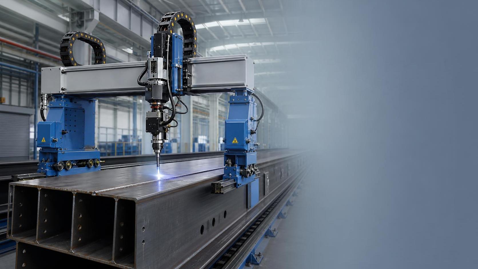
Why long seams expose travel instability
Long-seam welding is often treated as a welding-parameter problem: set the correct current, voltage, wire feed speed, travel speed, and shielding-gas flow, then let the robot repeat the program. In practice, project teams working on beams, pressure vessels, tank shells, large pipe sections, and structural assemblies know that this view is incomplete. A weld can begin within specification and gradually lose consistency because the robot or its carriage does not travel as steadily at the far end of the seam as it did at the start.
That is why the question behind a dual motor welding robot is usually not simply whether two motors are better than one. Project managers want to know whether a dual-drive arrangement will reduce rework risk on extended seams, whether it can maintain production rhythm on heavy workpieces, and whether the extra mechanical and control complexity is justified for the job mix.
Travel stability matters because welding is a moving process. Any change in actual torch speed, torch-to-work distance, seam position, or torch angle can alter heat input and bead formation. Over a short seam, minor fluctuations may remain within the process window. Over several metres, those deviations can accumulate into visible variation, poor tie-in, undercut, excessive reinforcement, lack of fusion, or a weld profile that triggers additional inspection and repair.
What a dual-motor drive changes mechanically
A conventional single-drive travel system applies propulsive force from one side of a carriage, rail, or driven wheel set. This can be entirely adequate for compact welding cells, short tracks, light tooling, and well-supported work. The limitation becomes more apparent when the moving system is long, heavily loaded, or exposed to uneven resistance. The drive force is no longer acting through a perfectly rigid, perfectly aligned structure. Small amounts of clearance in wheels, gearboxes, rail joints, cable carriers, and mounting interfaces can become significant over distance.
A dual motor welding robot generally distributes drive power across two coordinated drive points. Depending on the machine architecture, the motors may drive opposite wheels, separate sides of a gantry, paired travel modules, or two synchronized carriage elements. The engineering objective is not merely to double available power. It is to apply force more symmetrically, reduce the tendency for the system to skew, and maintain more predictable motion when rolling resistance changes.
On a long travel axis, a single-sided drive may produce a slight yaw or racking force. If one side advances marginally faster because of wheel slip, backlash, rail contamination, or unequal load, the carriage can try to rotate around its direction of travel. The result may be intermittent binding followed by release, often experienced as speed ripple. A dual-drive system can oppose that tendency when its motors, feedback devices, and mechanical transmission are properly matched.
It is important to be precise here: two motors do not automatically guarantee stable travel. Two poorly coordinated motors can create their own problems, including internal mechanical stress, oscillation, uneven wheel loading, or premature wear. The improvement comes from the combination of balanced mechanics, correctly tuned synchronization, adequate structural stiffness, and verification under real welding conditions.
How instability becomes a weld-quality issue
Robot travel is connected directly to heat input. When actual travel slows while current and voltage remain unchanged, heat input per unit length rises. The weld pool may widen, penetration may increase, and distortion risk can grow. When travel accelerates unexpectedly, the process may become colder than intended, increasing the possibility of inadequate fusion or inconsistent bead geometry. For multi-pass welding, an unstable first pass also changes the physical condition for subsequent passes.
Speed variation is only one pathway. Long-seam work may also be affected by lateral tracking error. If the welding torch departs from the joint centreline, the robot can place more metal on one side, lose sidewall fusion, or require seam-tracking corrections that are constantly compensating for mechanical movement rather than actual joint variation. In applications with narrow groove preparations, the available tolerance may be too small for this to remain a minor issue.
For project managers, the operational consequence is often more costly than the immediate weld defect. A long seam repaired after visual inspection, ultrasonic testing, radiographic testing, or pressure testing can disrupt fit-up, post-weld treatment, coating, and shipment. The welding robot may have completed its cycle, but the project schedule has not gained the expected benefit of automation.
Where the dual-drive approach is most relevant
A dual-drive travel system deserves closer attention when the fabrication task includes long, repeated welds and a meaningful cost of interruption. Typical examples include longitudinal seams on tanks and vessels, beam and box-section production, large-diameter pipe fabrication, wind-energy structures, heavy machinery frames, and modular process equipment. These are not identical applications, but they share a need for repeatable movement over a distance where mechanical imperfections become harder to ignore.
Several conditions tend to strengthen the case:
- Travel paths are long enough that rail alignment, frame deflection, and cable drag cannot be treated as negligible.
- The welding head carries substantial equipment, such as wire packages, seam-tracking sensors, torches, cameras, or multiple-process tooling.
- The process runs at controlled speeds where small changes can materially affect bead geometry.
- The workpiece or fixture introduces variable resistance across the travel path.
- Production involves repeated batches, making a reduction in variation more valuable than a one-time setup improvement.
- Access for manual correction is limited, expensive, or unsafe.
Conversely, a dual-motor configuration may provide limited economic value for a short, rigid, lightly loaded axis with a simple weld procedure and wide process tolerance. It should be selected because the operating conditions justify it, not because the architecture sounds more advanced.
Balanced drive is only part of the stability system
There is a common but incomplete claim that dual motors “eliminate” travel problems. In an actual workshop, travel stability is a system property. Motors are one part of that system.
Rail straightness and mounting quality remain fundamental. A precisely synchronized dual drive cannot compensate indefinitely for a rail that changes elevation, is insufficiently supported, or has poorly managed joints. The same applies to structural stiffness. A long gantry that flexes under changing cable load may produce torch movement even if the motor speed feedback looks stable.
Wheel contact and load distribution also require attention. A wheel that intermittently unloads, a worn drive surface, or contamination from grinding dust and spatter can produce slip. On some systems, dual motors can mask early symptoms because the second drive maintains movement. That may keep production running temporarily, but it does not remove the underlying maintenance issue.
Cable and hose management is frequently underestimated during project planning. Welding power cables, wire conduits, shielding-gas hoses, coolant lines, sensor cables, and extraction connections can generate a changing drag force along the axis. If the cable carrier is poorly sized or routed, resistance may increase at particular positions. That can appear in production data as a recurring defect location rather than a random process fluctuation.
Control synchronization determines whether the mechanics work together
In a well-designed dual-drive setup, the control system manages both motors as a coordinated axis. This can involve encoder feedback, speed matching, torque balancing, position comparison, and fault detection when the two sides diverge beyond an acceptable limit. The exact control strategy depends on the equipment design, but the acceptance question is consistent: can the supplier demonstrate stable motion under the expected load, speed, and duty cycle?
Project teams should avoid relying only on no-load demonstrations. A carriage can move smoothly without a welding package, without cable drag, and without the thermal and electrical environment of real production. Factory acceptance testing or site acceptance testing should replicate the highest-risk operating condition as closely as practical: maximum relevant travel length, representative torch package, production cable arrangement, anticipated seam speed, and workpiece geometry.
What to ask during specification and acceptance
The procurement specification should describe the production problem rather than only request “dual motors.” A supplier needs enough process context to size the mechanism and controls correctly. The most useful inputs include maximum travel length, carriage mass, payload distribution, welding process, required speed range, rail orientation, duty cycle, seam type, fixture design, and the planned use of seam tracking.
The following questions help convert a broad requirement into an evaluable solution:
- Are the two drives electronically synchronized, mechanically coupled, or both?
- What feedback is used to detect position or speed mismatch between sides?
- How does the system respond to a motor, encoder, gearbox, or traction fault?
- What rail straightness, levelness, and installation tolerances are required for the stated performance?
- What payload limit applies at the actual centre of gravity, rather than at an ideal balanced condition?
- How are cables and hoses supported throughout the full travel range?
- Can the system maintain the specified speed range under welding load rather than under no-load travel?
- What preventive maintenance is required for wheels, reducers, couplings, rails, and feedback devices?
- Which safety functions are included for emergency stop, overtravel, collision risk, and restart after interruption?
For projects involving CE-marked machinery, the project team should verify the scope of the supplier's conformity documentation and the final machine integration responsibilities. A CE marking on an individual component or positioning device does not, by itself, settle the compliance status of the completed automated welding installation. The final arrangement may include robot systems, guarding, material handling, welding power sources, extraction, and control interfaces that must be assessed as an integrated installation. Applicable standards and local regulatory obligations should be confirmed for the destination market【待核实】.
Do not separate robot travel from workpiece positioning
Long seams are often performed on cylindrical or heavy assemblies where part rotation is as important as torch travel. A stable welding robot cannot fully compensate for an unstable workpiece. Runout, inconsistent rotational speed, poor alignment between driven and idler supports, and inadequate load capacity can all alter the effective welding path.
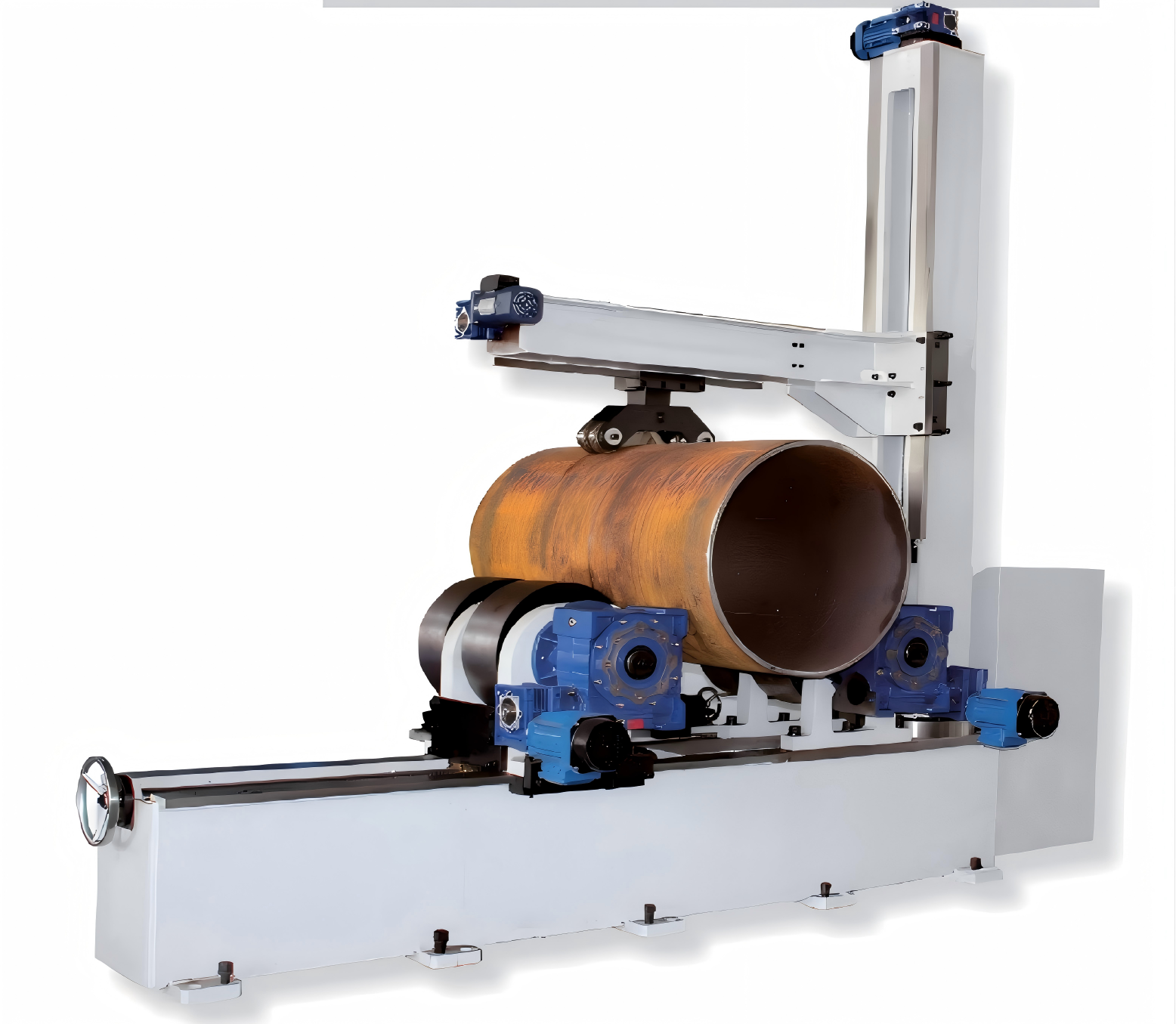
For large-diameter pipe butt welds, pressure-vessel shells, and cylindrical assemblies, an adjustable rotator may be the practical companion to an automated welding system. For example, a Bolt adjusting welding rotator uses adjustable support spacing to accommodate different workpiece diameters and rotates the workpiece during welding. Its relevance is not that it replaces robot travel control, but that it helps establish a more consistent relative movement between torch and joint.
When reviewing a rotator or similar positioning system, managers should check rated load, actual diameter range, wheel material, contact geometry, drive redundancy, speed-control range, and how the vessel will be restrained against axial movement. A variable-frequency drive may offer a useful speed range, but the key acceptance criterion remains steady rotation under the real eccentricity and load condition. A nominal speed setting is not proof of stable welding movement.
Commissioning should measure the complete process
Commissioning is where many otherwise sound projects lose time. The robot supplier may verify axis repeatability; the welding team may qualify the procedure; the fixture builder may validate part location. Yet the combined process has not been tested as a whole. Long-seam automation should be commissioned as one motion-and-welding system.
A practical validation sequence begins with mechanical inspection: rail alignment, anchor integrity, wheel contact, backlash, cable-carrier operation, and fixture rigidity. The next stage confirms motion performance at different positions along the travel axis, including starts, stops, direction changes, and the highest expected payload. Welding trials should then use representative joint preparation, material thickness, consumables, and production speed.
Rather than judging success only by a completed sample weld, record the conditions at which results were achieved. This should include commanded and actual travel speed where available, seam-tracking correction behaviour, arc-on time, weld profile observations, and inspection outcomes. If performance changes near a particular rail joint or at a certain cable-carrier position, the project team has evidence for correcting a mechanical cause before it becomes a recurring quality issue.
The investment case is about variation, not motor count
The value of a dual motor welding robot is easiest to understand as a reduction in process variation. On demanding long seams, balanced drive can improve resistance to skewing, uneven traction, and changing load conditions. That can support more consistent heat input, more reliable joint tracking, fewer corrective interventions, and better schedule predictability.
But the motor arrangement should not be evaluated in isolation. A robust project decision accounts for rail installation, structural stiffness, control synchronization, cable management, workpiece positioning, weld procedure tolerance, inspection requirements, and service access. The right question is not “does this machine have two motors?” It is whether the complete system can keep the torch and the joint in a stable relationship for the entire seam, throughout the production conditions the project will actually face.
search
Recommended Products
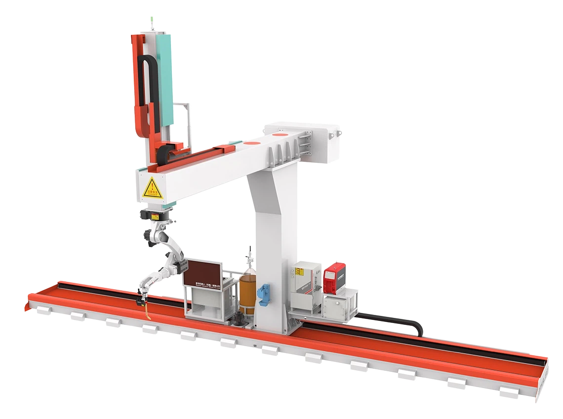
 9 axis cantilever type welding robot9 axis cantilever type welding robot for large steel workpieces with auto tracking, 3D import, and efficient CNC welding automation.
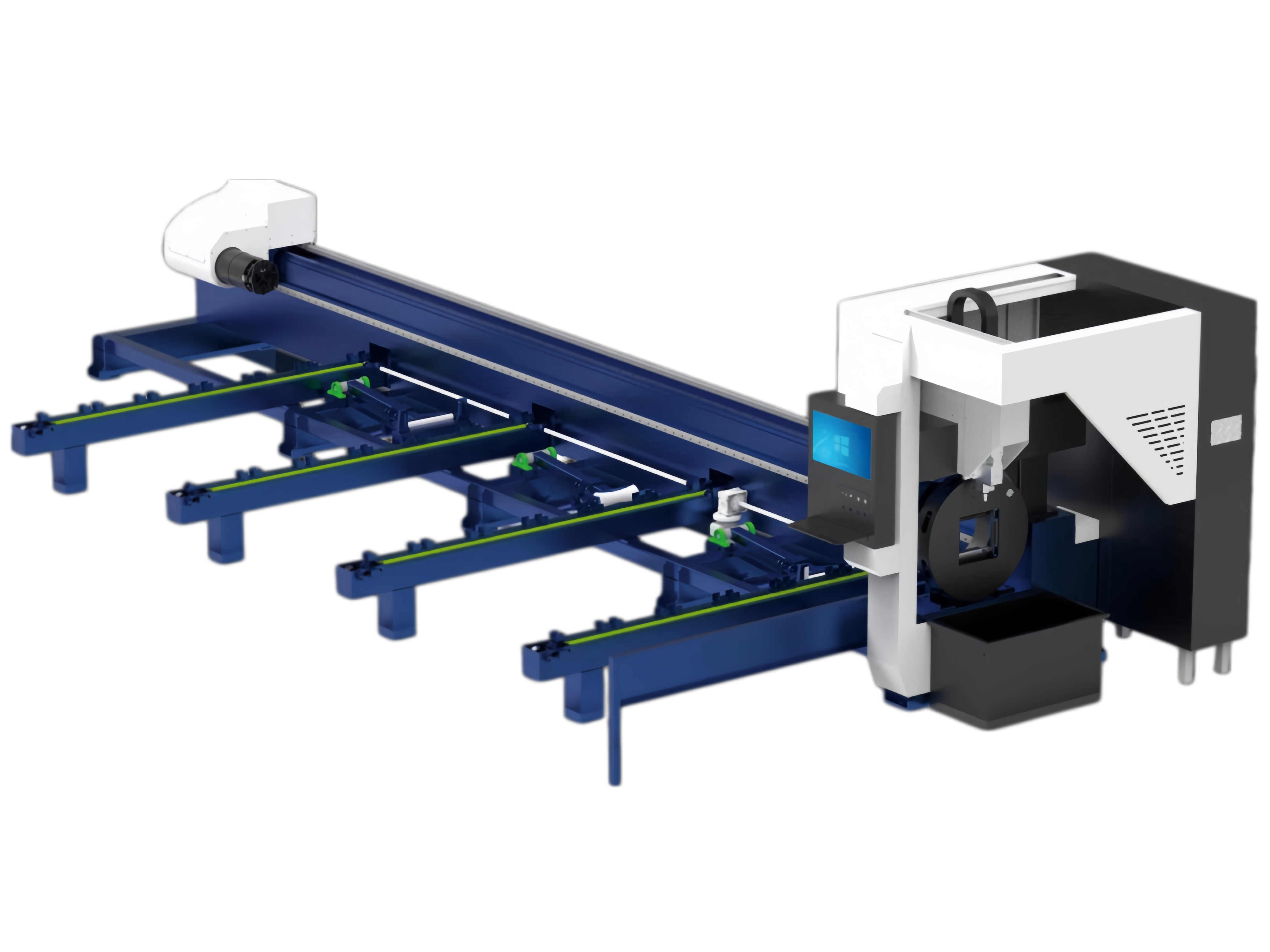
 Pipe cnc fiber laser cutting machine1.Introduction for Pipe cnc fiber laser cutting machine:
The laser cutting machine focuses the laser beam emitted from the laser source through the optical path system into a high-power-density laser beam. This laser beam is directed onto the surface of the workpiece, causing it to reach the melting point or boiling point. At the same time, the high-pressure gas coaxial with the laser beam blows away the molten or vaporized metal. Beveling & Milling Edge For Heavy TankThis series of heavy tank beveling and milling edge machines is a specialized, high-efficiency solution designed for beveling large storage tanks, pressure vessels, and heavy structural components. The main frame features an integrated welded construction followed by high-temperature stress-relief annealing, effectively eliminating internal stresses to ensure long-term dimensional stability and prevent deformation. The machine combines high-rigidity design with advanced control technology, purpose-built to handle the challenges of extra-thick plates and oversized workpieces.
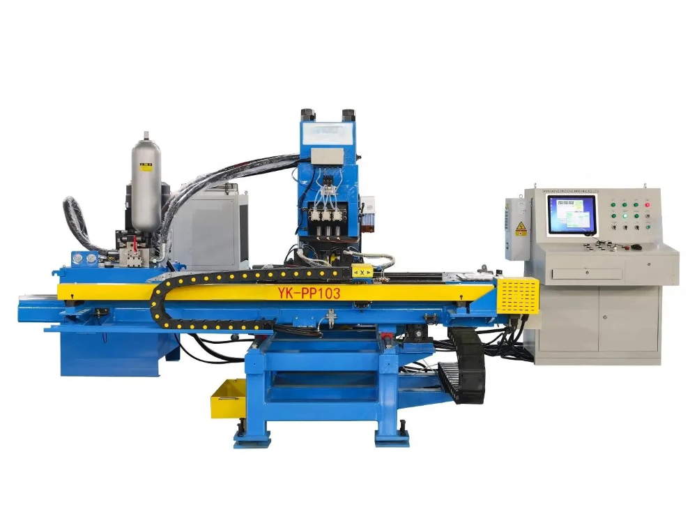
- CNC Punching And Marking Machine For Steel PlatesModels: YK-PP103 / YK-PPR103 / YK-PP104 / YK-PPR104
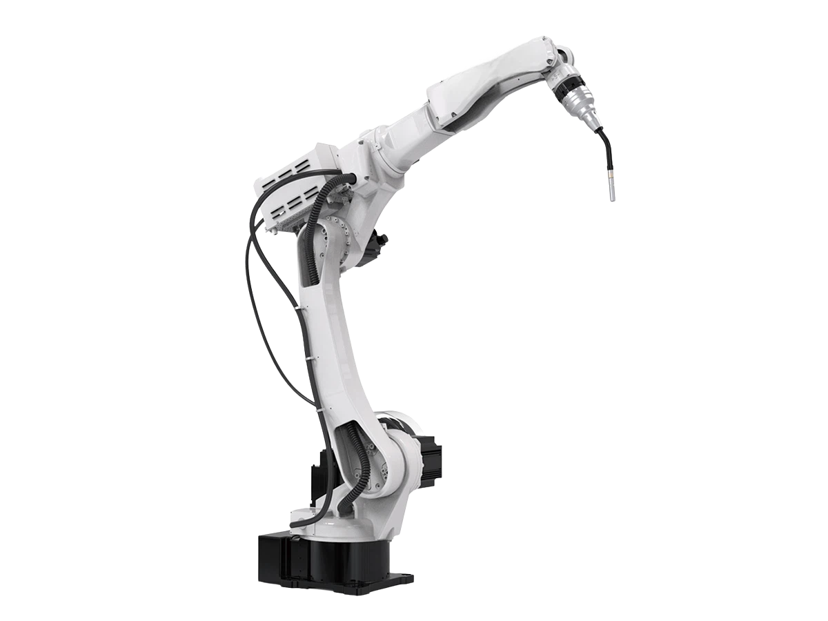
This series is a specialized CNC punching and marking machine designed primarily for steel plate processing in the steel tower industry. It is also well-suited for punching and marking applications across various other industrial sectors. - 6 Axis 2000mm ArmSpan MlG Industrial Welding RobotThis welding robot is designed for reliable arc welding in harsh production environments, featuring a long reach, stable repeatability, and flexible installation.
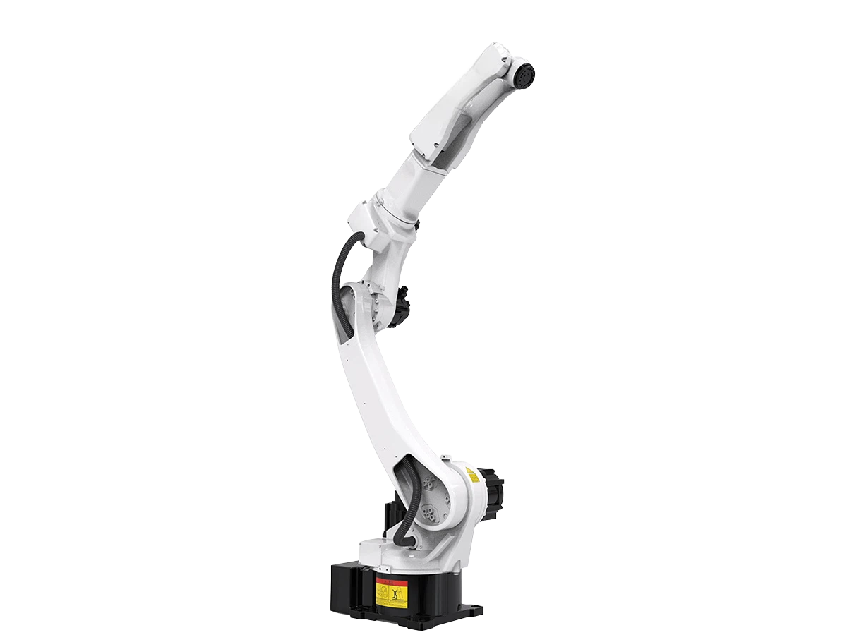
- Multipurpose Handing Robot BR20iB-20Explore the BR20iB-20 multipurpose robot for handling, welding, and cutting with 6-axis motion, ±0.08 mm repeatability, and flexible installation.

Send Us A Message