




Arc Welding Robot Basics: Processes, Components, and Suitable Production Tasks
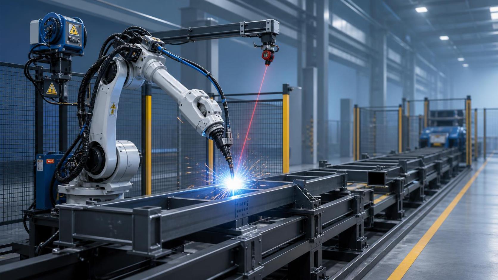
An arc welding robot is a practical solution for manufacturers seeking more consistent weld quality, higher throughput, and a safer production environment. But the decision to automate should begin with the workpiece and workflow, not with the robot itself. The relevant questions are whether the parts are repeatable enough, whether welding time is a real bottleneck, how often product designs change, and whether the factory can control fit-up, material preparation, and part handling.
For many fabrication businesses, robotic welding is not primarily a labor-replacement project. Its value is often found in reducing variation across shifts, making cycle times more predictable, documenting qualified procedures more reliably, and moving skilled welders toward preparation, quality control, complex repair, and higher-value manual work. The technology is most effective when it is treated as a production system rather than a stand-alone welding machine.
What an arc welding robot actually does
An arc welding robot combines an industrial robot arm with a welding power source, torch, wire-feeding equipment, control software, safety equipment, and usually some form of workpiece positioning or sensing. The robot moves the torch along a programmed path while the welding system establishes and maintains an electrical arc between the consumable wire electrode and the workpiece.
The basic principle is familiar to anyone involved in gas metal arc welding, but robotic operation adds repeatable torch angle, travel speed, stick-out, weaving movement, start-and-stop control, and coordinated parameter changes. If the part is consistently presented to the robot and the joint is within the system's tolerance range, the machine can repeat a qualified weld sequence for many cycles with limited variation.
That consistency is the key benefit, but it also exposes upstream weaknesses. A manual welder can often compensate for an incorrectly positioned plate, a widened gap, or inconsistent tack welding. A robot can use seam tracking or adaptive controls within a defined range, but it cannot turn poor fabrication discipline into a stable automated process. Robotic welding generally raises the importance of cutting accuracy, fixture strategy, tack quality, joint access, and incoming material control.
The main arc welding processes used in robotic cells
The most common process in robotic welding is gas metal arc welding, frequently referred to as GMAW or MIG/MAG welding depending on the shielding gas and material application. It is widely used for carbon steel structures, frames, brackets, fabricated assemblies, machinery components, and many stainless steel applications. Its relatively high deposition rate and continuous wire feed make it well suited to automation.
Within GMAW, the transfer mode matters. Short-circuit transfer can be useful for thinner materials, root passes, and positional work, although it may create more spatter if parameters and joint conditions are not well controlled. Spray transfer generally supports higher deposition rates on thicker material, often in flat or horizontal positions. Pulsed GMAW is commonly considered when a manufacturer needs more controlled heat input, better positional capability, or lower spatter across a wider operating range. The appropriate choice depends on material thickness, joint design, welding position, required appearance, distortion risk, and the applicable welding procedure.
Flux-cored arc welding may also be automated, particularly where higher deposition or tolerance for certain shop conditions is important. It can be effective for structural fabrication, but consumable selection, fume extraction, slag removal requirements, and surface-quality expectations should be evaluated carefully. A cell that needs manual cleaning between passes can lose much of its expected productivity.
Gas tungsten arc welding is less common in high-volume robotic structural work because it is slower and requires tighter process control, but it remains relevant for thin-gauge stainless steel, aluminum, precision assemblies, and applications where weld appearance and heat control are critical. Robotic plasma welding is used in more specialized situations. These processes can be highly capable, but their justification usually rests on a specific quality or material challenge rather than general throughput.
Components that determine real-world performance
The six-axis robot is the most visible component, but it is only one part of the cell. Reach, payload, repeatability, wrist configuration, cable routing, and access around the workpiece all affect whether the robot can reach every required weld. A robot with adequate nominal reach may still fail to access a joint because the torch collides with a fixture, the wrist cannot achieve the required angle, or a long torch neck limits clearance.
The welding power source and wire feeder determine how reliably the process can deliver the specified current, voltage, waveform, and wire-feed speed. Buyers should assess whether the power source supports the intended transfer modes and whether process packages are available for the materials and wire diameters in use. This is especially important when a factory expects to weld both light fabricated parts and heavier structural sections in one production area.
The torch system deserves close attention because it is a frequent source of downtime. A robotic torch must withstand repeated movement, heat, spatter, cable flexing, and occasional contact events. Torch cleaning stations, wire cutters, nozzle reamers, anti-spatter systems, and torch calibration routines are not peripheral accessories; they influence arc-start reliability and the amount of operator intervention required per shift.
Fixtures and positioners are equally important. Fixed fixtures can produce excellent repeatability for high-volume parts, while servo positioners can rotate a component so more welds are completed in a favorable downhand position. The tradeoff is that custom fixtures require capital, storage, maintenance, and changeover time. For businesses with frequent part changes or large structural assemblies, a less fixture-dependent arrangement may be more appropriate, provided sensing and part-location methods are sufficiently robust.
Safety systems should be considered part of the production design. A typical cell requires guarded access, emergency stops, interlocked doors or safety scanners, grounding, fume control, and clear procedures for loading, unloading, recovery, and maintenance. Compliance obligations vary by destination market and installation context. Manufacturers exporting equipment or operating across jurisdictions should confirm applicable machinery, electrical, and welding safety requirements rather than assuming a component-level certification covers the complete installed cell.
Where robotic arc welding fits best
The strongest candidates usually combine sufficient volume with a manageable degree of part variation. Repeated brackets, frames, chassis components, trailer parts, agricultural equipment, construction machinery assemblies, racks, and structural subassemblies are common examples. The work does not need to be identical forever, but the joints need to be accessible and the production team needs a practical way to load parts in a consistent orientation.
Part size also changes the automation approach. Small components may be loaded into compact cells with rotary positioners or dual stations. Medium fabricated assemblies may use dedicated fixtures and a robot mounted on a base or track. Long beams, columns, frames, and steel structures often require a robot travelling along a rail, a gantry-style arrangement, or multiple coordinated welding zones.
High-mix, low-volume fabrication is not automatically unsuitable. Traditional robot programming can make short production runs uneconomic when every new part needs extensive teaching. However, systems that use design data, vision or laser sensing, automatic path generation, and flexible placement can reduce the programming burden. Their success still depends on the quality of the digital model, the consistency of actual fabrication, and the ability to handle exceptions when the physical part does not match its drawing.
One example is the Cantilever type welding robot BR-2010A Pro/DG12, a configuration aimed at structural steel parts and fabricated assemblies with changing models. Its stated workflow uses direct TEKLA drawing import, laser-camera positioning, automatic program generation, and arc tracking for real-time weld correction. This type of arrangement is relevant when a fabricator wants to reduce manual teaching and fixture dependence, but it should be assessed as a whole system: drawing discipline, part tolerances, rail layout, loading method, and operator recovery procedures remain central to performance.
What an arc welding robot does not solve automatically
A common mistake is to calculate the return on investment using only the arc-on time of a skilled manual welder. In practice, the robotic cycle includes loading, clamping, scanning, program selection, pre-weld checks, welding, cleaning, unloading, and occasional recovery. If parts arrive slowly from cutting and fit-up, or if an operator spends too much time correcting poorly prepared assemblies, the robot may be underutilized despite having a fast theoretical welding speed.
Another misconception is that seam tracking eliminates the need for accurate parts. Seam tracking can compensate for moderate position variation during welding, and laser sensing can locate joints before the arc starts. Neither capability is unlimited. Large gaps, missing components, warped workpieces, poor tack placement, contaminated surfaces, or inaccessible joints can still create rejects, interruptions, or a need for manual intervention.
Automation also does not eliminate welding engineering. The joint design, wire, shielding gas, preheat requirements, interpass temperature, parameter windows, and weld sequence must still be suitable for the material and service condition. Where welds are subject to formal inspection, fatigue loading, pressure-service requirements, or customer-specific specifications, the robotic process should be qualified and verified through the same disciplined approach expected of manual welding.
Questions to ask before comparing equipment
Before reviewing robot brands or cell layouts, collect production facts. A useful initial review should cover the part family, annual and weekly volumes, material grades, thickness range, joint types, weld positions, required weld lengths, existing defect patterns, changeover frequency, available floor space, and current labor allocation. A short time study across several representative parts is usually more valuable than an estimate based on a single ideal job.
- Which parts account for the largest share of repetitive weld time?
- Are joint locations and dimensions stable after cutting, forming, and tack assembly?
- Can the robot access each weld without collisions or excessive torch-angle compromises?
- Will dedicated fixtures improve output enough to justify their cost and changeover effort?
- What happens when a part is out of tolerance, a wire feed fault occurs, or an arc start fails?
- Who will maintain consumables, validate programs, inspect welds, and recover the cell after a stop?
- Is fume extraction, electrical capacity, compressed air, and material flow adequate for the expected duty cycle?
Floor layout can become a decisive constraint for larger fabrication. For instance, a cantilever rail solution may be planned around a working footprint approximately 12 meters wide and 2 meters deep, with a 12-meter ground-rail support length. For workpieces longer than that but below approximately 25 meters, zone-based welding with two robots may be proposed. These figures are meaningful only when checked against actual loading clearance, safety separation, fixture dimensions, crane travel, downstream handling, and the need to service the equipment.
How to evaluate a proposed cell
Buyers should ask suppliers to demonstrate a representative part rather than relying only on generic videos or stated robot speed. The demonstration should include part loading assumptions, sensing or locating time, program preparation, welding sequence, cleaning requirements, and the handling of realistic fit-up variation. If possible, use a part that contains the difficult joints, not only the easiest fillet welds.
Acceptance criteria should be defined before purchase. They may include cycle time, weld appearance, dimensional distortion, penetration or macro-test results where relevant, arc-start success rate, rework rate, consumable usage, and the time required to switch to another part. The factory should also clarify what data, training, spare parts, remote support, and on-site commissioning are included. The most capable robot hardware has limited value if the local team cannot adjust approved programs or resolve ordinary production issues.
What is changing in robotic welding
The most relevant development is not simply faster robot motion. It is the increasing connection between engineering data and shop-floor execution. Drawing import, offline programming, laser measurement, vision systems, automatic parameter selection, and weld-path generation can reduce the time needed to introduce new work. This matters particularly for structural fabrication, where part dimensions may be large and product variation can be substantial.
At the same time, these tools increase dependence on disciplined data management. A model that lacks weld information, uses inconsistent naming, or does not reflect actual shop practices can create confusion rather than efficiency. Factories considering digital workflow integration should examine who owns the model data, who releases revisions, how changes reach the robot, and how the team prevents an obsolete program from being used on the floor.
An arc welding robot is therefore best viewed as a controlled production capability. It is most compelling where repeatable welding work, stable preparation, and a realistic material-flow plan already exist or can be established. For companies with variable structural work, the next question is not whether automation is possible, but whether sensing, programming, layout, and operating discipline can make flexibility economically useful rather than merely technically impressive.
search
Products Navigation
Send Us A Message