




Heavy-Duty Welding Robots for Large Fabrications: Duty Cycle and Payload Factors
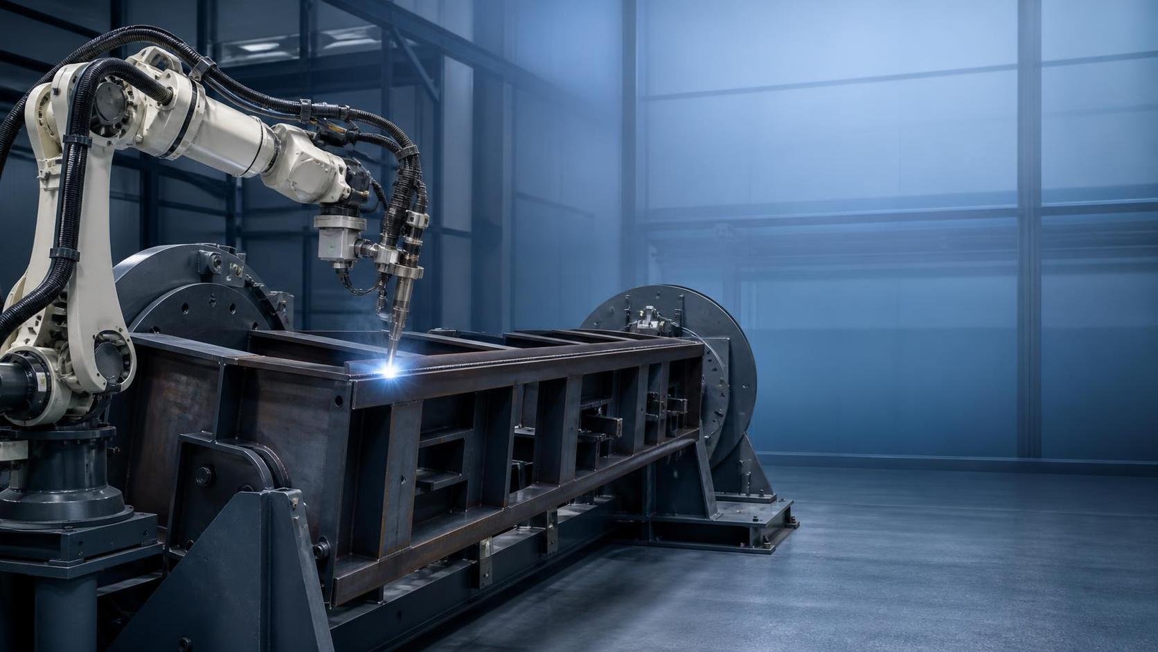
Large fabricated assemblies expose the cost of an underspecified robot quickly. Long weld seams, heavy torches, cable packages, seam-tracking hardware, positioners, and extended arc-on periods all place demands on the robot that may not be visible in a basic reach-and-price comparison. A heavy duty welding robot should be evaluated as part of a complete cell: the moving mass at the wrist, the expected thermal workload, the workpiece presentation method, and the time needed to recover from routine faults all affect the installed cost and usable output.
For steel structures, pressure vessels, large frames, beams, truck bodies, and similar fabrications, the most economical configuration is often the one that maintains path accuracy and availability under the actual duty pattern. A lower initial equipment price can lose its advantage when it requires reduced travel speed, frequent thermal pauses, limited tooling choices, or restrictive changes to part handling.
Duty Cycle Must Reflect the Real Welding Schedule
Duty cycle describes how long equipment can work within a stated period before cooling or recovery is required. It is often discussed for welding power sources, but it is equally relevant to the robot, torch, dress pack, wire feeder, fume extraction, and positioner. A cell may contain components with different limits. The practical limit is set by the component that reaches its allowable thermal or mechanical condition first.
Do not treat arc-on time as the only source of duty. During long fabrication programs, a robot also accelerates and decelerates repeatedly, holds awkward wrist angles, traverses between seams, and carries heated torch equipment close to the joint. High-deposition processes can increase heat exposure at the front end. Multi-pass welds may create long continuous sequences even when each individual pass appears short in an offline estimate.
A useful evaluation starts with a representative production mix rather than a single ideal part. Establish the expected number of welding hours per shift, the average arc-on ratio, the longest uninterrupted program, material thickness range, process type, joint access, and planned pauses for loading, inspection, and torch service. Distinguish between occasional peak demand and the normal schedule. Equipment intended for intermittent repair work may be acceptable at a lower continuous workload, while repetitive structural welding requires ratings that remain suitable through the planned operating pattern.
Ask for duty-cycle conditions in writing. The ambient temperature, welding current, travel pattern, robot speed, and tool configuration can influence published values. A rating stated without conditions cannot be compared reliably. It is also worth clarifying whether the proposed controller cabinet needs supplemental cooling, how heat is managed at the torch neck and cable package, and whether the cell layout leaves enough clearance for heat to dissipate.
Payload Is a Dynamic Load, Not a Torch Weight
Payload capacity is frequently misunderstood because the torch alone may be relatively light. The robot wrist normally carries a torch body, neck, wire or gas connections, collision sensor, mounting bracket, optional laser or tactile sensor, cable support hardware, and sometimes a cleaning fixture interface. The relevant figure is the full end-of-arm mass, including fittings that may be added after commissioning.
Mass alone is still incomplete. The center of gravity and moment of inertia have a strong effect on axis loading, acceleration limits, stopping accuracy, and gearbox stress. A long torch extension or a sensor mounted far from the flange can create a high moment even when the total mass remains below the nominal payload rating. A robot may technically lift the assembly but be unable to achieve the desired speed or repeatability at the planned reach.
Request the allowable payload curve across the working envelope, together with the permitted center-of-gravity offset and inertia values. Large fabrications often require welding near maximum reach, over a fixture, or around stiffeners where access forces the arm into extended positions. The capacity available in those postures may differ from the headline catalog payload. Collision recovery, rapid repositioning between seams, and coordinated motion with a positioner should be considered under the same tool load.
Reach, Stiffness, and Accuracy at the Joint
Reach determines whether the torch can access the weld, but it does not prove that the robot can hold a stable torch angle throughout the path. On large box sections and fabricated frames, the robot may need to reach over clamps, around gussets, or into a deep channel. Each condition should be reviewed with the actual torch geometry, not a simplified robot envelope.
Repeatability is useful for returning to programmed points, yet it should not be confused with absolute accuracy. A robot can repeat a taught position consistently while the part arrives with variation from cutting, fit-up, thermal distortion, or fixture wear. Large weldments commonly move after tack welding and after the first high-heat passes. Where part variation is meaningful, the cell may require touch sensing, through-arc seam tracking, laser guidance, adaptive welding procedures, or more controlled fixturing.
Cell rigidity also matters. A robot mounted on a weak pedestal, a flexible rail, or an uneven foundation can introduce vibration and position shift. The same applies to external axes carrying large workpieces. Confirm foundation requirements, baseplate design, anchor arrangement, rail alignment tolerances, and the stiffness of the fixture supporting the part. These details should be established before civil work and shipment, because corrective modification after installation can delay acceptance work.
Positioners and External Axes Change the Cost Equation
Reorienting a workpiece so that welding can remain in a favorable position often improves access and process stability. However, a positioner must be sized for more than the nominal workpiece mass. The calculation should include fixtures, clamps, extension arms, counterweights, cable carriers, and the workpiece center of gravity in every rotated orientation. An off-center load produces torque that may govern selection before total mass does.
For exceptionally long assemblies, a floor track or gantry arrangement can be preferable to moving the part repeatedly. That choice introduces additional installation and maintenance requirements: rail straightness, protective covers, travel cable management, homing strategy, guarding interfaces, and synchronization between robot and external axis. Coordinated motion needs validation with the real welding program, particularly where the torch tracks a long seam while the workpiece rotates.
Part flow should be mapped alongside motion planning. A cell that produces accurate welds but requires difficult crane access, slow fixture changeover, or repeated manual reclamping may create an upstream or downstream bottleneck. Consider the space for incoming material, tack assembly, finished weldments, inspection, rework, and safe separation between loading and automatic motion. Oversized workpieces also affect door dimensions, internal transport routes, lifting points, and container or flat-rack planning before delivery.
Welding Process Compatibility Cannot Be Assumed
The robot controller, welding power source, wire feeder, and process software need a defined interface. Confirm the supported process set, current and voltage feedback, weld schedule control, start and crater functions, wire retract behavior, fault signals, and parameter backup method. For thick steel, the planned joint preparation and deposition strategy should be reviewed together with the power source capacity. A robot with adequate payload cannot compensate for a process package that cannot maintain the required procedure window.
Consumable management deserves attention in large fabrication cells. Long programs increase the value of reliable wire feeding, torch cleaning, nozzle inspection, anti-spatter application, and contact-tip replacement. An automated cleaning station may reduce interruptions, but it consumes floor space and adds cycle actions. Its placement must be reachable without creating cable twists or interfering with loading. The cleaning routine should be based on actual spatter conditions rather than inserted at arbitrary intervals.
Pre-weld preparation has a direct effect on robotic consistency. Cut edges, scale, oil, burrs, and inconsistent root gaps can create unstable arc behavior and poor seam tracking. In steel plate fabrication, marking and hole location can also influence fixture referencing and assembly sequence. Where plate components are prepared before welding, programmed punching and marking may support traceable fit-up. For example, a CNC Punching And Marking Machine For Steel Plates can combine hole making and marking on steel plates within one setup, subject to the required workpiece size, thickness, and downstream reference method.
Cycle Time Should Include Everything That Stops the Arc
Quoted welding speed alone does not represent output. A credible cycle model includes loading, part clamping, program selection, safety confirmation, searching or sensing, torch cleaning, wire changes, robot travel, welding, positioner indexing, unloading, and inspection hold points. Small non-welding delays become significant when multiplied across a production schedule.
Program complexity can also change the usable cycle time. A simple fillet weld on a rigid assembly needs less sensing and fewer recovery paths than a multi-pass joint with variable fit-up. Ask to see how common interruptions are handled: wire burnback faults, collision trips, loss of arc, seam-search failure, or a part that has been loaded slightly out of position. Recovery should preserve the correct weld location and avoid forcing a complete program restart when that is unnecessary.
Offline programming can shorten cell preparation for recurring families of large structures, but its value depends on model quality and fixture consistency. CAD geometry, weld symbols, joint data, and coordinate references need an agreed handoff process. When fabrication drawings change, determine who updates programs, how revisions are identified, and how an obsolete version is prevented from reaching production. A vague ownership boundary at this stage can create expensive delays during launch.
Installation Scope and Maintainability Need Commercial Definition
A heavy duty welding robot installation involves more than delivery of the arm and controller. The quotation and technical scope should identify guarding, safety interlocks, fume extraction connection points, electrical supply requirements, compressed air quality, gas distribution, fixtures, external axes, welding package, installation supervision, programming, commissioning, and acceptance criteria. Items described only as “by others” should be assigned clearly before an order is released.
Maintenance access is a practical cost factor. Verify access to controller filters, cable connections, lubrication points, torch service stations, positioner drives, and rail components without dismantling guard sections or moving permanent equipment. Stocking recommendations should differentiate between routine consumables, wear parts with predictable replacement, and critical components with longer replacement lead times. Diagnostic logs, alarm history, parameter backup, and remote support arrangements should be defined in the technical documentation.
Acceptance should use representative parts and agreed weld criteria rather than an empty-cell movement demonstration. Confirm which material grades, thicknesses, joint configurations, filler metal, gas, fixturing, and inspection methods will be used. Where production parts are not available, test pieces should reproduce the relevant access restrictions and weld positions. This avoids accepting a cell under conditions that do not reflect the work it is intended to perform.
Common Specification Errors
- Choosing a payload based on the bare torch, then adding a collision sensor and seam-tracking equipment after the robot has been selected.
- Using maximum reach as proof of access without checking torch angle, cable clearance, fixture interference, and axis limits at each critical weld.
- Rating the cell from average daily welding time while ignoring the longest continuous job and the thermal condition of the torch and power source.
- Specifying a positioner from workpiece mass alone, without calculating fixture weight, eccentric loading, rotational torque, and the changed center of gravity after the part is turned.
- Leaving part datum strategy unresolved. A robot program cannot reliably correct for inconsistent fixture location or uncontrolled distortion without an appropriate sensing method.
The strongest technical proposal will connect robot payload and duty capability to the actual weldment, process, fixture, and material flow. That connection makes it possible to compare alternatives on total operating requirements instead of isolated catalog figures.
search
Products Navigation
Send Us A Message