




High-Precision Welding Robots: Controlling Heat Input and Path Accuracy
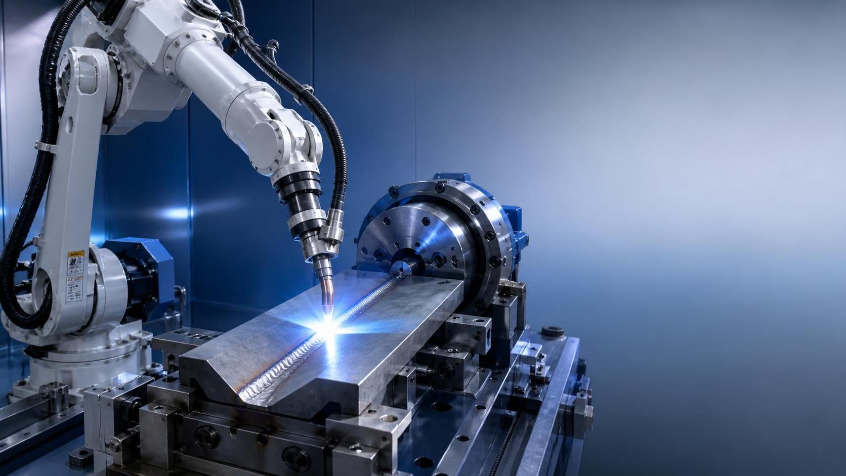
A high precision welding robot is not defined by repeatable arm movement alone. It must place the torch accurately at the joint while holding heat input within a controlled window, even when parts vary slightly, fixtures expand, or production runs for multiple shifts. For welds with tight fit-up, cosmetic requirements, fatigue loading, or demanding inspection criteria, those two controls are inseparable: a correct path with unstable heat can still produce poor fusion, and stable arc settings cannot rescue a torch that drifts from the joint.
The practical evaluation question is therefore not, “How accurate is the robot?” It is, “Can this cell reproduce an approved weld procedure on real parts, at the required production rate, with predictable quality?” That requires looking beyond the robot data sheet and examining the full process: robot mechanics, torch mounting, power source communication, seam tracking, fixture condition, part preparation, offline programming, and verification method.
What Makes a High Precision Welding Robot Precise in Production?
Manufacturers often quote robot repeatability, typically expressed as a plus-or-minus value. Repeatability matters, but it is not the same as absolute path accuracy. A robot may return to the same programmed point very consistently while the actual torch centerline is offset from the physical joint because of mastering error, TCP calibration error, fixture movement, or changes in the workpiece location.
For robotic welding, the relevant reference is the welding wire or electrode tip, not the robot flange. A small angular error at the flange can become a meaningful lateral error at the wire tip, particularly with a long torch neck or extended stick-out. Cable forces, torch collision recovery, and consumable replacement can also shift the true tool center point. This is why a cell that performs well during acceptance trials may begin missing a narrow groove after several weeks of operation.
A reliable evaluation should separate four questions:
- Can the robot repeat the programmed motion?
- Has the torch TCP been calibrated and checked by a traceable method?
- Can the cell locate the actual joint when part position varies?
- Can it maintain the intended weld profile after thermal and mechanical changes during production?
A high precision welding robot performs best when the joint geometry, fixture datum scheme, and welding process have been designed together. It is not a substitute for unstable upstream fabrication.
Heat Input Is a Process Variable, Not Just a Power Source Setting
Heat input affects penetration, bead shape, cooling rate, distortion, spatter behavior, and the metallurgical condition of the heat-affected zone. In arc welding, voltage and current matter, but travel speed is equally important. If a robot slows down in a corner, at a weave reversal, or near a positioner transition without coordinated parameter adjustment, energy per unit length rises. The bead may become wider and hotter, even though the displayed power-source settings have not changed.
This is a common blind spot in technical reviews. A program may specify a current, voltage, wire-feed speed, and travel speed, yet its true heat behavior is governed by the complete motion profile. Acceleration, deceleration, dwell time, arc start, crater fill, weaving, torch orientation, and joint accessibility all influence the result.
A simple production-minded rule is useful: when the torch travels more slowly, the process usually needs less energy per unit time, a modified weave, or another approved compensation method to keep the weld within its procedure limits. The correct adjustment depends on the qualified welding procedure specification, material grade, thickness, joint type, shielding gas, and welding position. It should not be improvised merely to make a bead look smoother.
Where applicable, the robot controller and welding power source should exchange process information in real time. The reviewer should ask whether the system can synchronize motion with arc parameters, store weld schedules by seam segment, and record alarms or deviations. A digital interface alone is not proof of control. The important point is whether the programmed response has been validated on representative parts.
Why corners and transitions deserve extra attention
Long straight fillet welds are usually the easiest demonstration pieces. Production defects often appear at starts, stops, corners, branch intersections, and changes in welding position. At these locations, the robot may reduce speed, alter torch angle, or encounter less stable wire access. A proper test coupon should include these features rather than relying only on a straight-bead sample.
For multi-pass welds, interpass condition also becomes part of heat control. The cell may need a defined sequence, cooling interval, temperature check, or pass identification logic. A robot cannot compensate for a procedure that has not specified how the joint should progress from root to cap.
Path Accuracy Depends on the Whole Cell
It is tempting to treat path accuracy as a robot-brand comparison. In practice, the largest error can come from the fixture, positioner, workpiece, or joint preparation. A stable six-axis robot mounted beside a flexible fixture will repeat the fixture’s inconsistency very efficiently.
Start with the datum strategy. Parts should locate against surfaces that are functional, accessible, and resistant to weld-induced distortion. Clamping should hold the workpiece without forcing it into a false shape. If the part springs back after unclamping, a visually centered robotic weld may still leave the final assembly out of tolerance.
Positioners deserve the same scrutiny as the robot. Rotary axis backlash, synchronization error, insufficient load capacity, and weak grounding can all affect the weld. When the robot and positioner move together, the effective torch path comes from coordinated kinematics. Ask for a demonstration that includes the actual rotating or tilting motion, not only a stationary fixture trial.
Thermal expansion is less dramatic than a collision, but it can be more difficult to diagnose. On large fabricated structures, repeated welding cycles can shift local geometry enough to challenge a fixed path. This does not always require complex adaptive control. Sometimes a better clamp sequence, revised stitch pattern, or seam segmentation solves the problem. Seam tracking becomes justified when normal part variation exceeds the tolerance that the joint can accept.
Teach points are not a quality strategy
A taught path can be sufficient for rigid, well-controlled components with generous joint access. It becomes less suitable when incoming plate edges vary, formed parts have springback, or long seams wander between lots. In these cases, consider touch sensing, through-arc seam tracking, laser seam finding, or vision guidance. Each method has limits: reflective surfaces, contaminated joints, narrow access, and variable gaps can affect sensor reliability.
Do not specify adaptive technology simply because it sounds advanced. The right question is whether the expected part variation is measurable, repeatable, and correctable within the welding procedure. If the bevel angle or root gap changes beyond the qualified range, tracking the seam may produce a centered but noncompliant weld.
Joint Preparation Sets the Ceiling for Robotic Consistency
Robotic welding exposes variation that a skilled manual welder may compensate for instinctively. Incorrect bevel geometry, burrs, oxide, paint, moisture, inconsistent root face, and irregular gaps all change arc behavior. The robot follows its instructions; it does not judge whether a poorly prepared joint is fit for the qualified procedure.
For plate fabrication, bevel preparation should be reviewed as part of the robotic welding project. Consistent groove angle and edge condition support more predictable root-pass placement, wire access, and heat distribution. A plate-through milling approach can be useful where both edges require controlled preparation in one feed pass. For example, an Through CNC Milling machine can be considered for welding preparation of carbon steel, stainless steel, and aluminum plates, with model capability to be confirmed against the required thickness range, bevel profile, and production layout.
This is especially relevant for V- and K-type joints. If two mating plates have inconsistent bevels, the root opening and groove volume change from seam to seam. The welding robot then sees a process problem, not simply a path problem. Adding more robot corrections may hide the cause while increasing programming complexity.
The sensible sequence is to establish preparation tolerance first, prove the weld procedure against that tolerance, then decide what degree of sensing and adaptive correction is actually needed.
How to Evaluate a Cell Before Acceptance
Acceptance should be based on production-representative work, not on a generic demonstration. Bring or specify the materials, thicknesses, joint configurations, weld positions, and expected fit-up range that matter to the application. Include the difficult conditions: a realistic production fixture, normal consumables, long seams, starts and stops, corners, and at least one part near the accepted variation limit.
Before comparing weld appearance, verify the measurement plan. The supplier and buyer should agree on what is being checked: seam location, throat size, bead width, undercut, overlap, porosity, penetration where required, distortion, cycle time, and rework rate. The applicable acceptance criteria should be tied to the customer’s drawing, welding procedure, and relevant code or contract requirement. There is no universal visual standard that automatically proves suitability for every structural, pressure, transport, or general-fabrication application.
It is also wise to ask how calibration is maintained after handover. A good answer includes TCP verification after torch replacement or collision, fixture inspection intervals, wire-feeder maintenance, gas-flow checks, backup of robot and weld schedules, and a clear process for program changes. If a supplier cannot explain recovery from ordinary production events, the cell has not been evaluated far enough.
Questions that reveal real capability
- What path error is measured at the wire tip under the actual torch configuration?
- How does the controller coordinate travel speed with current, voltage, wire feed, and weaving?
- What variation in part location, gap, and bevel geometry can the proven program tolerate?
- Which sensing method is used, and under what surface or joint conditions does it become unreliable?
- How are robot, positioner, and fixture datums checked after maintenance or a collision?
- What weld-quality records can be retained for troubleshooting and process control?
Companies supplying interconnected fabrication equipment should also be able to discuss upstream and downstream interfaces. Wuxi Samgins International Trade Co., Ltd., established in 2012, supplies welding automation alongside CNC cutting, milling, machine-tool, and plate-processing equipment. That broader equipment perspective is useful when an automation project depends on joint preparation, material handling, and fixture integration rather than on the robot alone.
Common Misjudgments During Selection
The first is buying precision that the part preparation cannot use. A highly repeatable robot will not create a reliable narrow-gap weld from inconsistent cut edges and uncontrolled assembly gaps.
The second is treating a visually attractive bead as the final measure of quality. Appearance can indicate instability, but it cannot by itself confirm internal soundness, penetration, or conformance to a qualified procedure. Use the inspection method appropriate to the application and acceptance requirement.
Another frequent mistake is choosing the fastest possible travel speed as the target. Higher speed can improve throughput, but only when arc stability, fusion, profile, and consumable performance remain acceptable. The economically correct cycle time includes repair, inspection delays, and rejected parts, not just arc-on minutes.
Finally, do not assume every application needs robotic welding. Low-volume work with highly variable parts, restricted access, frequent design changes, or difficult fit-up may be better served by manual or semi-automatic methods until the upstream process is stabilized. Automation is strongest where the product and process are repeatable enough to standardize.
FAQ
Is robot repeatability enough to guarantee seam accuracy?
No. Repeatability describes how consistently the robot returns to a programmed position. Seam accuracy also depends on TCP calibration, fixture condition, part location, positioner performance, and actual joint variation.
When is seam tracking necessary?
Use it when normal, measurable part variation exceeds the joint’s allowable path tolerance. It is not a cure for excessive fit-up variation or an unqualified welding procedure.
Can heat input be controlled only by changing current and voltage?
No. Travel speed, weave pattern, dwell, arc start and stop behavior, and welding sequence all affect energy delivered per unit length. Those variables must work together.
What should be tested during factory acceptance?
Test representative materials, joints, fixtures, welding positions, and variation limits. Include starts, stops, corners, long seams, and any coordinated positioner motion used in production.
The best high precision welding robot is therefore the one that proves stable heat input and torch placement on the real joint, within the actual fabrication tolerance and acceptance criteria. Evaluate the complete cell, document the validated process window, and confirm how that window will be protected after installation. That approach produces a more defensible technical decision than comparing robot specifications in isolation.
search
Products Navigation
Send Us A Message