




Choosing blade tooth pitch for a band saw machine cutting tubes
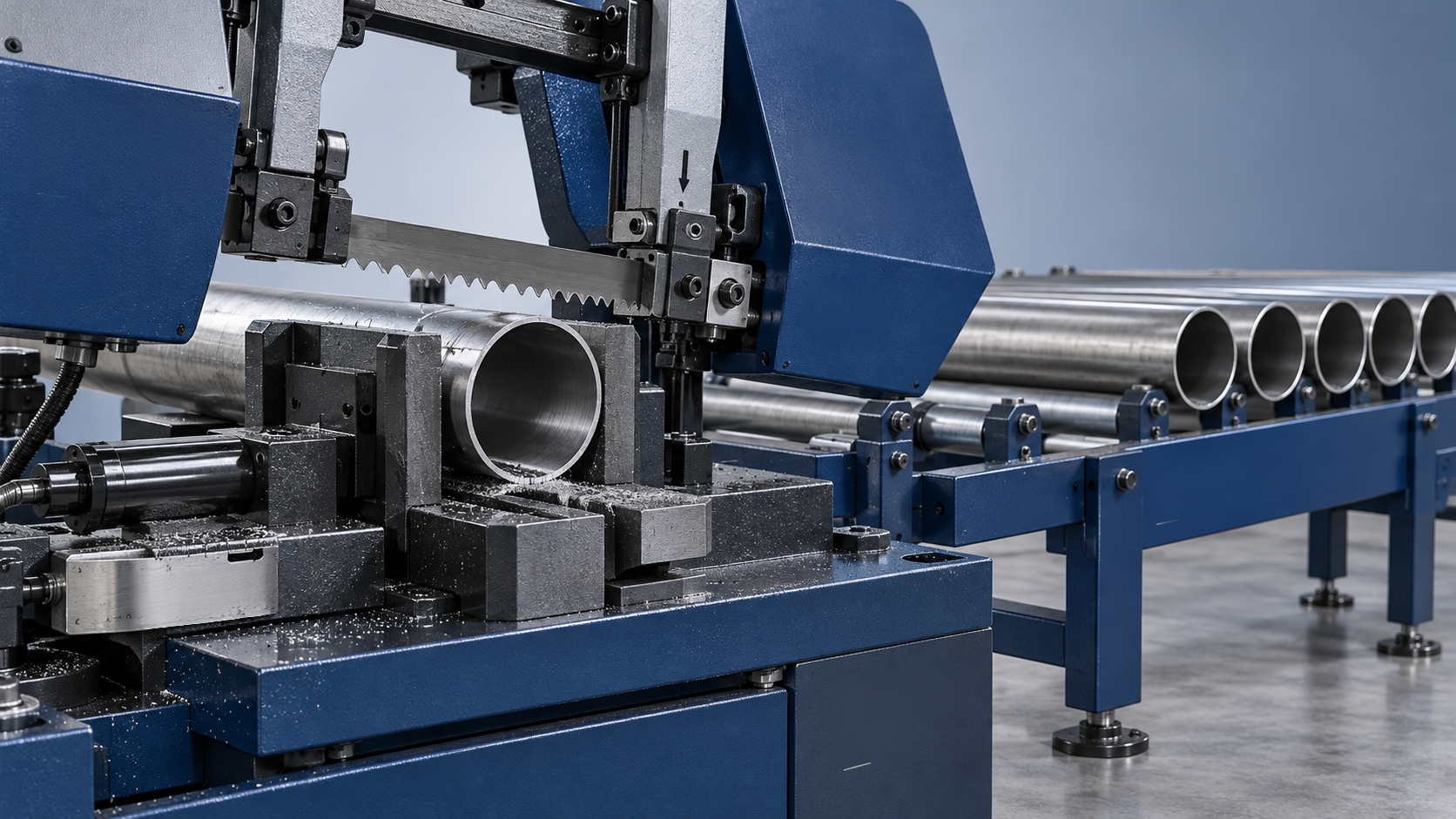
When a band saw catches the wall of a tube, the result may be a sharp knock, stripped teeth, heavy burrs, or a damaged workpiece. Select tooth pitch from the tube’s wall thickness and changing cutting cross-section, then check it against the blade manufacturer’s tube-cutting chart. Outside diameter alone is not enough: a large, thin-wall tube can need finer teeth than a smaller, thick-wall tube.
On a saw band machine, the aim is to keep enough teeth engaged to avoid snagging while leaving enough gullet space to carry chips out of the cut. Thin walls generally favor finer pitches; thicker walls and heavier cutting sections allow coarser pitches. Variable-pitch blades often suit tubes because engagement changes during the cut, but they cannot compensate for loose clamping or excessive feed pressure.
Read the blade marking before choosing a pitch
Tooth pitch is commonly expressed as teeth per inch, or TPI. A higher TPI means finer teeth with smaller spaces between them. A lower TPI means coarser teeth with larger gullets. Those gullets carry chips, so choosing the finest blade available is not automatically the safest option.
A marking such as 10/14 TPI identifies a variable-pitch pattern rather than a single uniform spacing. The changing tooth spacing helps reduce repetitive excitation and vibration. It is useful when a blade repeatedly enters and leaves material, as happens across hollow sections and bundles.
Pitch is only one part of blade selection. Tooth set provides clearance for the blade body, while tooth geometry affects how aggressively each tooth enters the wall. Blade material must also suit the tube material. Two blades with the same TPI can behave differently if their rake angles, sets, or intended applications differ.
Before comparing pitches, confirm the blade length, width, and thickness approved for the machine. A suitable tooth pattern on an incorrectly sized blade is not a workable solution.
Wall thickness comes first, but geometry changes the load
A useful preliminary check is the familiar guideline of keeping at least about three teeth engaged in the material where practical. Too few teeth can concentrate the cutting force on individual tips. However, hollow sections create interrupted engagement, so this guideline is a screening tool—not a complete pitch-selection rule.
For a continuous length of material along the blade path, the approximate number of engaged teeth is:
Engaged teeth ≈ material length in millimeters × TPI ÷ 25.4.
For example, a 3 mm continuous section at 14 TPI spans only about 1.7 tooth spacings. This illustrates why thin walls are vulnerable to coarse teeth. It does not prove that 14 TPI is unsuitable for every 3 mm-wall tube: the actual contact length depends on tube geometry, blade position, and cutting angle.
Do not calculate engagement from the outside diameter as though the tube were solid. Equally, do not add separated walls together and assume they provide the same support as one continuous section. Each tooth still encounters an unsupported transition when it crosses the hollow center.
Round tubes
During a horizontal cut through a round tube, the blade initially meets a short region near the top. Contact then increases through the curved wall. Farther into the cut, the blade crosses two separated wall sections; near breakthrough, engagement changes again. The machine’s feed system must cope with this changing resistance without driving teeth aggressively into the wall.
This is why outside diameter and wall thickness both belong in the blade supplier’s selection chart. Wall thickness indicates the risk of insufficient local tooth support, while diameter influences the cutting geometry and the extent of engagement changes.
Square and rectangular tubes
A square tube held with a flat face upward presents a broad top wall, followed by two side walls. A rectangular tube’s orientation can therefore change cutting resistance substantially. Rotating it may alter engagement, but that is only appropriate when the vise and supports can hold the new orientation securely. Never trade stable clamping for a theoretically better tooth-contact pattern.
Narrow the choice using the actual cutting arrangement
Use the following comparison to decide which part of the manufacturer’s pitch chart deserves attention. It gives selection direction rather than universal TPI values.
For adjacent variable pitches, such as 10/14 and 14/18 TPI, the finer option generally gives more tooth support across short contact lengths. The coarser option generally offers more chip space. Treat that comparison as a reason to consult the appropriate chart and run a controlled trial, not as a recommendation for every tube size.
Material matters as well. Stainless steel can work-harden when teeth rub instead of cutting, so simply selecting a fine pitch and slowing the feed excessively may create another problem. Aluminum can load the gullets with chips. Match blade speed, lubrication, and tooth geometry to the material rather than expecting pitch alone to control heat.
Bundles need a separate assessment
A bundle increases the total amount of metal cut at once, but each tube still contains thin walls and gaps. Selecting pitch from the bundle’s overall width as though it were solid stock can leave individual teeth striking unsupported edges too aggressively.
Record tube diameter or section dimensions, wall thickness, tube count, and packing arrangement. Include the overall bundle dimensions when requesting a recommendation. A single row and a stacked bundle do not present the same engagement pattern, even when they contain the same number of tubes.
Clamping often becomes the limiting factor. Tubes inside a bundle may move even when the outer tubes appear secure. Use the machine’s approved bundle-clamping arrangement, and keep the bundle properly supported. Movement can chip teeth and resemble a pitch problem; changing blades without correcting it only repeats the damage.
Run a controlled trial instead of changing several settings
A trial cut should establish whether the pitch works throughout the stroke, not merely whether the blade can finish one part. Observe entry, the middle of the cut, and breakthrough separately.
- Record the starting conditions. Note tube material, dimensions, wall thickness, blade specification, pitch, speed, and feed setting. Include bundle layout or tube orientation.
- Check the machine first. Inspect guides, blade tension, chip brush, coolant delivery, and workpiece support according to the machine manual. Position adjustable guides appropriately for the stock.
- Follow the blade’s break-in instructions. New tooth edges may require reduced cutting load initially. Do not judge pitch using an aggressive first cut on an unbroken-in blade.
- Begin with the recommended material settings. Keep feed controlled as the blade enters the first wall and approaches breakthrough. Keep guards in place; never reach toward a moving blade or collect moving chips.
- Inspect the completed cut after stopping safely. Check burrs, squareness, wall deformation, chip evacuation, and tooth condition. Compare more than one cut before making a production decision.
- Change one variable at a time. Where the evidence points to pitch, compare an adjacent recommended pitch while keeping other conditions consistent.
Stop the trial if teeth are breaking, the tube shifts, or abnormal vibration develops. Continuing with missing teeth can overload the remaining teeth and make the original cause harder to identify.
Use the cutting symptoms to separate pitch from setup faults
Listen for where the noise occurs. A knock confined to initial contact suggests an entry problem; vibration throughout the stroke calls for a broader check of clamping, guides, tension, and blade condition. A cut that starts normally but becomes progressively harder can indicate chip accumulation or changing engagement.
Chip appearance provides supporting evidence, but it is not a standalone pitch gauge. Very fine debris can indicate rubbing; overloaded gullets can indicate insufficient chip space. Interpret either observation alongside material, speed, feed, and tooth condition.
Keep downstream requirements separate from blade selection
Choose acceptance criteria before the trial. A tube going directly into a welded assembly may require a square end, limited burr, and no crushed wall. If deburring is necessary, inspect the as-cut edge first so finishing does not hide tooth snagging or wall deformation.
In assemblies combining cut tubes with bent sheet-metal brackets, a Torsion bar synchronize CNC press brake serves the separate sheet-bending stage. Its torsion-shaft synchronization and wedge-type deflection compensation relate to bending control, not saw-blade pitch. Bracket accuracy should therefore be assessed independently from tube-end quality.
Once a pitch works, record its usable limits: material, wall-thickness range, section sizes, orientation, and bundle arrangement. Review that choice when any of those conditions changes. If the wall is too thin to achieve stable engagement with the available blades, ask the blade supplier about a dedicated thin-wall tooth form or the machine supplier about suitable feed control. Increasing TPI indefinitely can exchange tooth impact for rubbing and chip congestion.
search
Products Navigation
Send Us A Message