




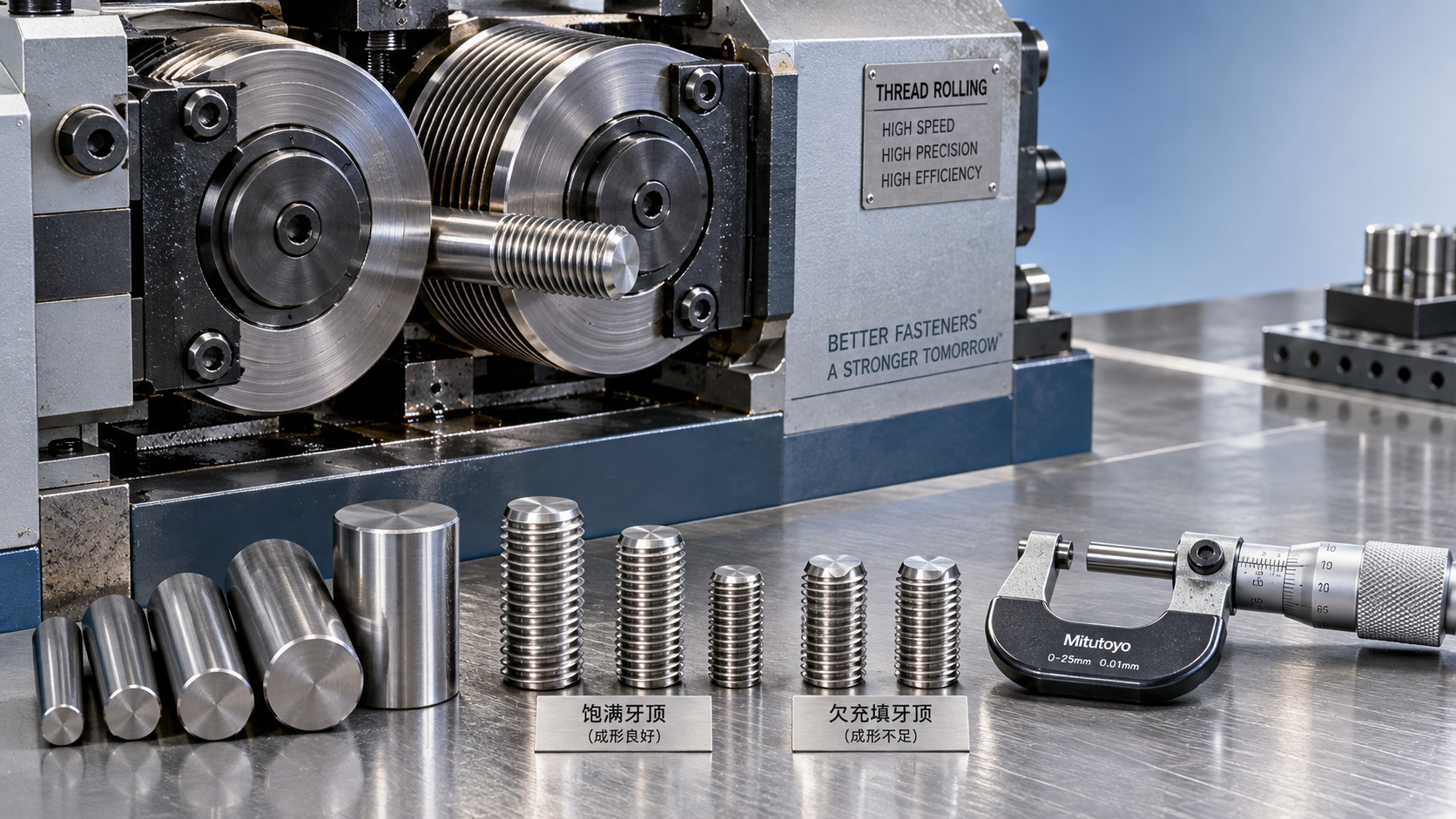
How blank diameter affects a high-speed thread rolling machine
Blank diameter is a small dimension with a major influence on thread quality, rolling force, and die life. Its acceptable range requires process validation.
On a high speed thread rolling machine, an oversized blank can increase forming loads and promote overfilling, while an undersized blank may produce incomplete crests.
For technical evaluators, the challenge is defining a blank diameter and tolerance that suit the thread geometry, material, and rolling process across normal production variation.
The strongest approval evidence combines measured blank dimensions, finished thread inspection, and production-speed trials. Nominal pitch diameter alone cannot establish a reliable blank specification.
Why blank diameter matters more than its small size suggests
Thread rolling forms external threads by displacing material rather than removing it. The starting diameter therefore controls how much metal enters the forming region.
During engagement, the dies push material away from thread roots and toward the crests. Correct material volume helps the finished profile develop within specified limits.
If excessive material enters the die profile, forming resistance can rise sharply. Depending on the setup, excess metal may produce oversized dimensions or folded surfaces.
If insufficient material is available, additional penetration cannot necessarily create the missing crest volume. Instead, adjustment may distort other thread dimensions or increase unnecessary loading.
Diameter also affects initial contact and workpiece rotation. Variations can change how blanks enter the dies, particularly when feeding and engagement happen within short cycles.
Technical evaluation should therefore connect blank diameter with dimensional capability, machine loading, surface integrity, and feeding reliability. Checking finished thread size alone leaves important uncertainties.
Should the blank diameter equal the thread pitch diameter?
For many conventional external threads, a diameter near the pitch diameter provides a useful starting estimate. It should remain an estimate until trials establish suitability.
The final requirement depends on thread profile, crest and root geometry, material response, die design, and process configuration. Applicable drawing requirements must guide the decision.
Material redistribution is not perfectly confined to one cross-section. Some processes produce axial movement or elongation, which can change the relationship between starting and finished dimensions.
For illustration, the basic pitch diameter of an M10 × 1.5 ISO metric thread is approximately 9.026 mm. That value describes theoretical thread geometry only.
It is not an approved rolling blank diameter or tolerance. Actual preparation requirements need confirmation against the selected tolerance class, tooling, material, and inspection results.
Ask the tooling supplier for a recommended starting range and its assumptions. Confirm whether that recommendation applies to your thread length, material condition, and machine configuration.
What oversized and undersized blanks do to thread quality
An oversized blank supplies more material than the intended profile may accommodate. Typical warning signs include increased loading, excessive major diameter, and disturbed crest formation.
Overfilling can encourage laps or folds where displaced material flows unfavorably. Their occurrence also depends on die geometry, penetration, lubrication, and the material’s forming behavior.
An undersized blank commonly leaves crests incompletely developed or produces an insufficient major diameter. Pitch diameter may also become unacceptable, depending on the adjusted setup.
These defects should not be diagnosed from diameter alone. Worn dies, misalignment, inconsistent material, and lubrication problems can produce similar symptoms during production trials.
Use paired measurements to investigate: record each blank’s diameter and roundness, then inspect its finished thread. This connects incoming variation with actual forming outcomes.
Functional gauges provide essential acceptance information, but they do not characterize every defect. Add dimensional measurements and surface examination appropriate to the drawing and application.
How diameter variation affects force, stability, and die life
Higher forming demand can result from increased blank diameter, particularly as the available die profile approaches full filling. The load response need not remain linear.
A setting that performs well at the average diameter may become unstable at the upper limit. Trials should deliberately include blanks near both specification boundaries.
Monitor forming force where instrumentation permits. Hydraulic pressure, motor current, or machine load signals can support comparison, but they require interpretation for the specific equipment.
Peak loading and cycle-to-cycle variation are both useful. A stable average can conceal occasional overloads associated with oversized blanks, poor entry, or inconsistent material condition.
Repeated excessive loads can contribute to die wear or damage. Actual die life also depends on tooling material, lubrication, alignment, contamination, and the rolled material.
Do not accept a promised tool-life improvement based solely on tighter blank control. Request comparative operating data with equivalent tooling, material batches, and production conditions.
Why a successful slow trial may fail at production speed
At higher throughput, feeding, engagement, forming, and release must remain coordinated within shorter cycles. Small inconsistencies can become more visible as stoppages or rejected parts.
A slower trial may provide more forgiving handling conditions or a different forming schedule. It cannot automatically establish capability at the intended production rate.
Changes in speed can alter lubrication behavior, temperature, and material response. Their effects depend on machine design, lubricant delivery, and the specific rolling operation.
Run the proposed high speed thread rolling machine at the intended rate after setup verification. Include sufficient continuous operation to observe temperature and loading trends.
Measure blanks and finished threads under defined temperature conditions. Thermal expansion can otherwise obscure whether an apparent dimensional shift comes from forming or measurement practice.
Record interruptions alongside dimensional results. A process that produces acceptable samples while requiring frequent feed corrections may still fail the intended capacity and consistency targets.
How to specify blank tolerance without unnecessary machining cost
A useful blank tolerance is the widest range that consistently produces compliant threads under validated conditions. Arbitrarily tight limits can add preparation cost without demonstrated benefit.
Start by establishing a practical target diameter with the tooling supplier. Then test controlled diameter levels around that target using representative production material and preparation methods.
Include the proposed lower limit, target, and upper limit. Record the actual measured diameter of each trial group rather than relying only on machining settings.
Hold other variables sufficiently consistent to interpret the result. Document material condition, die settings, lubrication, speed, and thread length before comparing the diameter groups.
Map acceptable thread results against loading and surface condition. Set specification limits inside the demonstrated operating window, allowing appropriate margin for production and measurement variation.
Also specify relevant roundness, taper, and surface requirements. A blank can satisfy one diameter reading while presenting substantially different contact conditions around its circumference.
What incoming measurements should evaluators require?
Measure diameter at several axial positions across the rolling zone and in multiple angular orientations. This helps identify taper, ovality, and localized preparation defects.
Use calibrated equipment with adequate resolution and a suitable measurement method. Measurement uncertainty must be small enough to support decisions near the proposed tolerance limits.
Check surface condition before rolling, including burrs, scale, and machining marks. Their significance depends on depth, location, material condition, and the final thread integrity requirements.
Confirm material grade and the condition delivered to the machine. Hardness variation or differences in prior processing can change forming behavior even when diameters match.
Review entry chamfers and the transition into adjacent features. Their geometry can influence engagement, thread runout, and how consistently the blank seats during loading.
Keep blank measurements traceable to production lots and finished results. This makes it easier to distinguish a preparation problem from machine drift or tooling wear.
What a convincing machine acceptance trial should demonstrate
An acceptance trial should use the actual thread specification, representative material, and intended production configuration. Convenient sample parts may conceal the application’s most demanding conditions.
Agree on inspection methods before testing begins. Define required thread dimensions, functional gauging, surface checks, and any mechanical testing specified for the finished component.
Sample across the run, including startup and stable operation. Repeat relevant checks after a tooling adjustment or restart when these events occur in normal production.
Evaluate blanks near both diameter limits at the intended output rate. Confirm that acceptable results do not require separate undocumented settings for each diameter group.
Where capability indices are requested, first establish process stability and measurement suitability. A short demonstration with selected samples cannot substantiate long-term production capability by itself.
The trial report should connect output quality with measured input variation and loading. Include rejects, stoppages, adjustments, and operating conditions so the conclusion remains reviewable.
Where automated handling helps—and what it cannot establish
Consistent loading helps preserve the conditions established during trials. Automated handling can support repeatable presentation, provided the gripper, locating features, and machine interface are suitable.
For cell planning, the Multipurpose Handing Robot BR20iB-20 offers six-axis motion, a maximum working radius of 2102 mm, and a specified wrist payload of 20 kg.
Its stated repeatability is ±0.08 mm. This describes robot positioning performance under specified conditions; it does not establish blank dimensional accuracy or finished thread capability.
Evaluate payload with the gripper and workpiece included, and check permitted wrist moments and inertia. Reach alone does not confirm access throughout the required handling path.
Validate the complete loading cycle against machine throughput, clearances, and interlocks. Fixture location and gripper compliance also influence how consistently parts reach the rolling position.
Automation cannot supply missing material to an undersized blank or prevent overfilling from an oversized one. Incoming dimensional control remains necessary within an automated cell.
How to turn the findings into an equipment decision
When evaluating suppliers, request an application-specific proposal linking blank preparation, tooling, machine capacity, and inspection. This provides stronger evidence than an isolated maximum-speed specification.
Wuxi Samgins International Trade Co., Ltd. supplies thread rolling machines alongside other metalworking equipment. Buyers should request recommendations tied to their drawings and representative materials.
For a high speed thread rolling machine, prioritize a demonstrated operating window covering expected blank variation. Confirm that loading remains within the machine’s applicable limits.
Compare total production implications, including blank preparation cost, rejection rate, tooling consumption, and interruptions. Faster nominal output has limited value if diameter sensitivity undermines usable production.
Approve the blank specification and machine settings together after representative trials. Record the accepted material condition, diameter limits, tooling, lubrication, speed, and inspection requirements.
Blank diameter becomes manageable when its effects are measured and controlled. A validated operating window gives technical evaluators a defensible basis for equipment and production approval.