




How to size a band saw machine for cutting large steel bundles
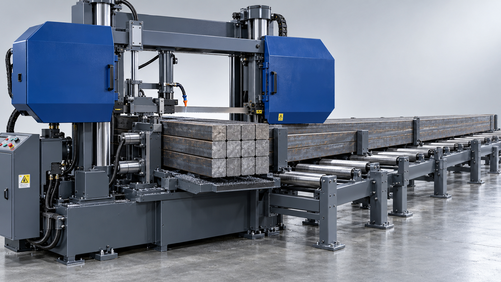
A band saw sized only to the outside dimensions of a steel bundle can still be unsuitable for the job. Its cutting envelope may accommodate the stock, while its clamping system cannot restrain individual bars, its blade cannot maintain straightness through the cut, or its material-handling equipment cannot support the load. Reliable sizing starts with the complete bundle and production cycle—not the maximum cutting-capacity figure in a catalogue.
The right machine is the smallest configuration that can safely hold, feed, and cut the required bundle while meeting the specified cut quality and sustained output. Cutting capacity, blade system, structural rigidity, drive performance, and load handling must therefore be evaluated together.
Define the bundle as an operating load
“Large steel bundle” is not a sufficient specification. A tightly stacked bundle of square solid bars behaves differently from round bars, thin-wall tubes, or mixed structural sections, even when the outside dimensions are identical.
Before comparing machines, establish:
- Maximum and normal bundle width and height, including uneven stacking and protruding members.
- Individual section dimensions, number of pieces, and packing arrangement.
- Steel grade, delivery condition, and any significant hardness variation.
- Incoming stock length, total bundle mass, and required cut lengths.
- Permissible length variation, squareness error, burr condition, and surface damage.
- Required good pieces per shift, batch sizes, and frequency of material changes.
Distinguish three different sizing cases: the largest geometric envelope, the heaviest handling load, and the most demanding cutting condition. These may belong to different products. A wide bundle of thin-wall tubes can govern clamping and tooth selection, while a smaller bundle of alloy-steel solids governs cutting time and blade loading.
Shipping straps should not be treated as a substitute for the machine’s workholding system. Their retention or removal must follow an agreed loading and cutting procedure. Members must remain restrained when the blade breaks through, including on the discharge side.
Check usable capacity, not just nominal width and height
A published rectangular cutting capacity does not automatically represent usable bundle capacity. Top clamps, jaw geometry, fixtures, blade-guide positions, and the loading path can reduce the available space. Round capacity figures are especially unsuitable as a shortcut for sizing rectangular bundles.
Ask for a drawing showing the bundle inside the actual clamping arrangement. It should identify the maximum permitted width and height with the bundle attachment installed, the minimum size that can be clamped securely, and the blade’s clearance throughout its travel.
For illustration, an eight-by-eight stack of 75 mm square solid bars has a nominal envelope of 600 × 600 mm. A machine rated at exactly 600 × 600 mm leaves no allowance for imperfect stacking, dimensional variation, or fixture interference. The necessary clearance should come from the measured loading envelope and the machine layout, rather than an arbitrary percentage added to catalogue capacity.
Capacity must also be checked at the intended cutting angle. If the work requires mitre cuts, both the available envelope and the length of blade engagement change. A straight-cut capacity cannot be carried over unchanged to angled cutting.
This is also an equipment-category boundary. A Hydraulic Swing Beam Shear is intended for sheet-metal shearing; its sheet thickness or backgauge positioning specifications do not establish suitability for cutting bundles of bars, tubes, or structural sections.
Bundle mass can govern the installation before cutting power does
Calculate steel mass from the actual metal cross-sectional area, not the bundle’s outside rectangle:
Bundle mass = total metal cross-sectional area × stock length × material density.
Using approximately 7,850 kg/m³ for steel, the 64-bar example has a metal area of 0.36 m². At an incoming length of 6 m, its calculated mass is about 16,956 kg, or 17 tonnes. This is an illustrative geometric calculation, not a machine load rating.
A saw with sufficient cutting capacity may still be incompatible with that load. Check the permitted workpiece load at the saw bed, the feed carriage capacity, and the ratings of each roller-table section. These ratings must be assessed against actual support spacing and load distribution, not simply added together.
The handling assessment should include:
- Local loads where the bundle rests on individual rollers.
- Unequal load distribution caused by bowed stock or uneven ends.
- Resistance during indexing, including acceleration and roller friction.
- Support of the remaining stock and the separated bundle after breakthrough.
- Floor loading, anchoring, crane access, and safe loading clearances.
Short cut lengths create a separate problem: the discharged pieces may lose stable support even though the incoming bundle is well supported. The discharge arrangement must prevent tipping, separation, or uncontrolled movement without obstructing the blade.
Match the blade system to changing engagement
Blade sizing is not simply a choice of width. Blade width, thickness, tooth pitch, tooth form, blade material, tension, and guide spacing work together.
A wider blade can provide greater resistance to deflection, but only within a machine designed for it. Wheel geometry, tensioning capacity, guide design, and frame stiffness must support the specified blade. Installing a heavier blade does not correct a weak saw frame or poorly supported workpiece.
The critical geometry is the metal encountered along the blade’s path. In a tightly packed row of square solids, engagement can approach the full bundle width. In round-bar bundles, contact length changes as the blade descends. In tube bundles, the blade repeatedly enters and leaves individual walls.
That difference matters because teeth need both adequate support and sufficient gullet capacity to carry chips out of the cut. Excessively fine pitch can overload the gullets during long engagement in solid material. Excessively coarse pitch can leave too few teeth engaged in thin walls, increasing tooth impact and stripping risk.
Request a blade recommendation for each representative bundle—not just for the steel grade. The recommendation should specify blade dimensions, material, tooth form, pitch range, and operating limits. Variable-pitch blades can help manage vibration, but they do not eliminate the need to match tooth geometry to the section arrangement.
Blade material should follow the material condition and production requirement. Bimetal and carbide-tipped blades impose different requirements on speed range, rigidity, and operating discipline. A carbide option should be evaluated as a compatible cutting system, not assumed to provide an automatic productivity increase.
Evaluate stiffness and clamping before relying on motor power
Large bundles expose weaknesses in the complete force path: blade, guides, saw head, workholding, and machine base. A high-power motor cannot compensate for movement within that system.
For demanding straight cuts through wide bundles, a rigid guided head deserves close evaluation. Twin-column designs can provide symmetrical support, while pivot-head designs have a different motion geometry. Neither label guarantees performance; guide spacing, bearing condition, head stiffness, and feed-control quality remain decisive.
Clamping needs to prevent both movement of the bundle and movement of members within it. Side pressure alone may not restrain upper rows. A suitable arrangement may require top clamping, shaped jaws, or a fixture matched to the section geometry.
More clamping pressure is not always better. Thin-wall tubes can deform before the bundle becomes securely restrained. Ask how pressure is regulated, how the clamps contact uneven stacks, and whether restraints remain effective throughout indexing and separation.
The unsupported blade span should also be minimized within the machine’s permitted setup. Adjustable guides must approach the work without colliding with clamps or protruding stock. Catalogue capacity measured with widely separated guides says little about achievable cut straightness under load.
Specify power and feed control as a working combination
Motor kilowatts alone are a poor predictor of bundle-cutting performance. Required power depends on steel condition, cutting speed, tooth geometry, feed, engagement, and blade condition. Compare the drive’s usable torque and speed range, transmission characteristics, and continuous-duty capability—not just its nameplate rating.
Feed control matters because blade engagement changes during the cut. A fixed descent rate that works through one portion of a round-bar bundle may overload teeth when contact increases elsewhere. The machine should provide controlled cutting force and feed adjustment appropriate to that changing load.
Ask the supplier to explain what the control system actually measures. Hydraulic pressure, motor current, and blade-deflection sensing provide different information. “Automatic feed” is not enough detail to establish how the machine responds to tooth overload, vibration, or material variation.
Coolant delivery and chip removal also belong in the sizing decision. Chips retained in gullets or carried back into the cut can increase heat, damage teeth, and disrupt cutting. Check coolant access across the cutting zone, blade-brush adjustment, filtration, and conveyor capacity for the proposed duty.
Convert the output target into a permissible cycle time
A bundle produces multiple pieces per stroke, but production capacity depends on the complete cycle. Include cutting, blade return, unclamping, indexing, reclamping, and discharge. Loading, blade changes, and planned adjustments must also be accounted for without being counted twice.
Required cutting cycles = required good pieces ÷ usable pieces produced per cycle.
Maximum average cycle time = net available production time ÷ required cutting cycles.
Suppose the requirement is 1,280 good pieces from a 64-bar bundle. That requires 20 successful cutting cycles, assuming every member yields an acceptable piece. If net available production time is 336 minutes, the complete cycle must average no more than 16.8 minutes.
If indexing, clamping, return, and discharge consume 4.8 minutes, the cutting portion has a 12-minute allowance. For the illustrative solid-bar bundle, that corresponds to an average cross-sectional cutting rate of 360,000 mm² ÷ 12 minutes, or 30,000 mm²/min.
This is a required performance threshold, not evidence that a particular machine or blade can achieve it. The supplier must substantiate the rate for the specified steel, bundle arrangement, blade, and quality limits. Cutting rates quoted for single bars or different material conditions are not directly transferable.
Long indexing distances and repeated feed strokes can materially change the result. Confirm whether the required cut length can be advanced in one stroke and how repeated strokes affect positioning, bundle stability, and cycle time.
Make the acceptance cut prove the proposed size
A defensible saw band machine selection ends with an agreed performance test, not a comparison of catalogue maxima. The test material should represent the conditions governing the purchase: bundle geometry, steel grade, hardness, incoming length, and required cut length.
Define measurable acceptance criteria before testing:
- Complete cycle time under the agreed handling conditions.
- Cut-length variation across individual bundle members.
- Squareness in both relevant planes, including bars from different stack positions.
- Burrs, clamp marks, deformation, and evidence of member movement.
- Blade loading, chip evacuation, and stability over consecutive cuts.
A single fast cut with a fresh blade cannot establish sustained throughput or blade life. Agree on a test duration that can demonstrate repeatability, and require any blade-life projection to state its assumptions separately from measured results.
The final specification should tie the guaranteed bundle envelope to its mass, section arrangement, material condition, blade configuration, and quality requirement. Oversizing is justified when it supplies necessary clearance, stiffness, handling capacity, or verified production reserve. Extra cutting capacity alone is not a reason to buy a larger machine—and it is not a substitute for proving the intended bundle-cutting duty.
search
Products Navigation
Send Us A Message