




Why does a band saw machine drift when cutting solid steel bars?
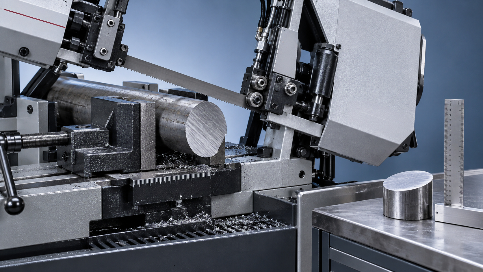
A cut that starts square and finishes crooked is frustrating, especially when the next operation depends on an accurate blank. When a band saw machine drifts while cutting solid steel bars, the usual causes are uneven tooth cutting, insufficient blade support, excessive feed force, or movement in the workpiece. Several of these problems can occur together.
A saw band machine needs the blade, guides, clamping system, and cutting settings to work as a matched system. Simply slowing the machine may improve one cut without solving the underlying fault. The better approach is to identify when the deviation begins, inspect the most likely components, and verify each adjustment with a controlled test cut.
Read the cut before changing the machine
“Drift” can describe two different problems. The blade may wander through the bar and leave a curved cut face, or it may produce a relatively flat face that is consistently out of square. That distinction helps separate cutting instability from alignment errors.
These patterns are clues, not definitive diagnoses. Remove loose chips and burrs before checking a cut face with a square. Where the finish is rough, compare measurements at several points rather than trusting a single contact point.
Before inspecting the blade, guides, wheels, or vise, stop and isolate the machine according to its lockout procedure. Secure any raised saw head as the manufacturer requires. Never adjust guides or clear packed chips beside a moving blade.
Why solid steel bars expose small setup problems
Solid stock creates sustained cutting resistance. Unlike tubing, there is no hollow section to reduce the amount of metal being removed. In a round bar, the engaged cutting width also changes as the blade travels from the narrow top section toward the center and then toward the bottom.
This changing engagement affects cutting load and chip volume. A feed setting that seems comfortable at entry may overload the teeth in the wider middle section. If the blade cannot clear chips or resist the resulting force, it can bow or twist away from the intended cutting plane.
Steel grade matters as well. Mild steel, alloy steel, and stainless steel do not require identical cutting conditions. Hardness, surface scale, and work-hardening behavior can all change how the blade performs. Use the blade supplier’s recommendations for the actual material and stock size, not a setting remembered from a different job.
Check the blade before compensating with feed settings
Uneven tooth wear can steer an otherwise sound machine
Band saw teeth create a kerf wider than the blade body through their tooth set or cutting geometry. If teeth on one side become damaged or worn differently, the cutting forces become unbalanced. The blade can then pull sideways even when the machine alignment appears correct.
Look for chipped teeth, missing tooth groups, uneven wear, and metal welded onto the cutting edges. Possible causes include interrupted engagement, poor break-in, hard surface scale, excessive feed, and recutting chips trapped in the kerf.
A blade may still remove steel while no longer producing an acceptable straight cut. If the teeth are clearly damaged, changing the feed cannot restore their geometry. After checking for machine faults that could damage the replacement, test with a suitable, known-good blade.
Tooth pitch must suit the engaged section
An excessively fine pitch can leave too little gullet space for chips during a deep cut in solid steel. Packed gullets increase resistance and heat. An excessively coarse pitch may leave too few teeth engaged near the top of a round bar, increasing the risk of tooth impact and stripping.
Select pitch using the blade manufacturer’s chart for the material and cutting section. Variable-pitch blades can help control vibration, but they do not compensate for incorrect feed, poor clamping, or worn guides.
Also confirm that blade width, thickness, and construction are approved for the machine. A wider blade is not automatically an upgrade if the wheels and guides were designed for a different size.
Tension needs verification, not guesswork
Insufficient tension allows the blade to deflect under cutting pressure. Excessive tension can overload the blade, bearings, and other machine components. Neither condition should be corrected by estimating how tight the blade “feels.”
Use the machine specification and the blade supplier’s guidance, with a suitable tension gauge where required. Check whether the displayed value represents blade stress, hydraulic pressure, or another measurement; these are not interchangeable. Persistent tension loss deserves investigation for hydraulic faults, tensioning mechanism wear, or other causes.
Blade support: the most overlooked saw band machine check
The cutting section needs enough support to resist twisting, but guides must not pinch the blade or damage its teeth. Position movable guide arms as close to the workpiece as the machine instructions allow, leaving clearance for the vise and the complete cutting stroke.
Long unsupported spans make sideways deflection more likely. This is particularly noticeable when a machine remains set up for large stock while cutting much smaller bars.
- Side guides: Check carbide pads or rollers for wear, contamination, correct clearance or preload, and alignment.
- Back-up bearings: Inspect for free movement and damage, including wear associated with excessive feed load.
- Guide arms: Look for looseness or movement at their mounting points.
- Blade seating: Confirm the blade follows the manufacturer’s specified path through the guide assembly.
Do not tighten every guide until the blade is forced into position. Incorrect guide pressure can create heat, accelerate wear, and introduce the twist you are trying to remove. Follow the model-specific adjustment procedure.
If a sound blade and correctly adjusted guides still produce a consistently angled cut, check machine geometry. The blade cutting plane, vise reference face, and head movement must maintain the intended relationship throughout the stroke. A worn pivot or loose guide mounting can cause errors that a simple static square check misses.
Adjust cutting load without creating a new problem
Operators often increase feed when production falls behind. With solid steel, that can push the blade beyond its ability to cut and evacuate chips. The blade then bends instead of advancing cleanly, particularly through the wider section of a round bar.
Make a controlled reduction in feed within the recommended operating range and observe whether straightness improves. If it does, excessive cutting load is likely contributing—but still check whether a dull blade or poor support is making the original setting unsuitable.
Very low feed is not a universal cure. Teeth that rub instead of cutting can generate heat and accelerate wear. This is especially undesirable with materials prone to work hardening. Blade speed and feed should be selected together.
Use chip appearance as supporting evidence. Powdery chips may suggest rubbing, while unusually heavy chips can indicate excessive load. Chip form varies with material and tooth geometry, so also consider cutting sound, vibration, motor load, blade condition, and the finished face.
A chattering blade, repeated tooth impacts, or an obvious increase in cutting resistance is a reason to stop and investigate—not to force the cut through.
Clamping, support, and coolant can change the result
A round bar that rolls slightly in the vise can make a correctly aligned blade appear to drift. Clean the jaws and seating surfaces, check for wear, and confirm the stock is held securely using the machine’s approved clamping arrangement.
Long bars need appropriate external support. A support positioned too high can lift the stock away from its intended seating; one positioned too low can allow sagging and unstable loading. Check the bar’s position after clamping rather than assuming the support height is correct.
The cutoff piece also needs safe handling. Near breakthrough, a shifting offcut can pinch the blade or damage teeth. Use the manufacturer’s recommended cutoff-support method without creating a binding condition.
Coolant problems usually contribute indirectly to drift by increasing heat, friction, and tooth wear. Check that coolant reaches the cutting zone, the concentration matches the fluid supplier’s recommendation, and nozzles or filters are clear. Inspect the chip brush as well: if it is not removing chips effectively, the blade may carry them back into the cut.
A practical test sequence that avoids wasted adjustments
Changing tension, feed, speed, and guide position together may produce a better cut, but it leaves you uncertain about the cause. Instead, establish a safe baseline and test one variable at a time.
- Record the job: Note steel grade, bar size, blade specification, blade age, speed, feed setting, and where deviation begins.
- Inspect while isolated: Check teeth, blade installation, tension, guides, clamping, supports, coolant delivery, and chip removal.
- Correct obvious faults: Replace damaged consumables and restore settings to the manufacturer’s recommendations before testing.
- Make a controlled cut: Keep material and setup consistent. Break in a new blade according to its supplier’s procedure.
- Measure the result: Check both squareness and face shape, recording deviation across the bar section.
- Change one parameter: Adjust feed or another relevant setting within the approved range, then compare results.
If drift continues with a known-good blade and verified setup, maintenance should examine guide mountings, head pivots, wheel bearings, blade tracking, and feed-control behavior. Wheel or structural adjustments should be handled by personnel qualified for that machine.
Keep sawing accuracy separate from downstream handling
Fabrication shops often combine cutting, machining, and welding, but each operation needs its own workholding solution. Wuxi Samgins International Trade Co.,Ltd supplies mechanical equipment across these areas, including CNC cutting machines, machine tools, and welding equipment. When requesting assistance, provide the saw model, blade details, material specification, and measured cut error so the discussion starts with evidence.
For a separate downstream task—supporting and rotating cylindrical fabrications during welding—a Self aligning welding rotator may be relevant. The supplied range includes rated-load options from 5 to 200 tonnes and controlled rotation for pipes, tanks, and pressure-vessel components. It is not a remedy for saw drift or a substitute for approved bar support; selection requires checking workpiece weight, diameter, and the specific model’s limits.
The most reliable route to a straight cut is not one dramatic adjustment. It is a sound blade, verified tension, correctly aligned guides, secure stock, and cutting conditions matched to the steel. Once those are working together, repeatable cut quality becomes much easier to maintain—and the next machining operation no longer has to compensate for an avoidable sawing error.
search
Products Navigation
Send Us A Message