




Does a 2000mm reach welding robot reduce fixture repositioning?
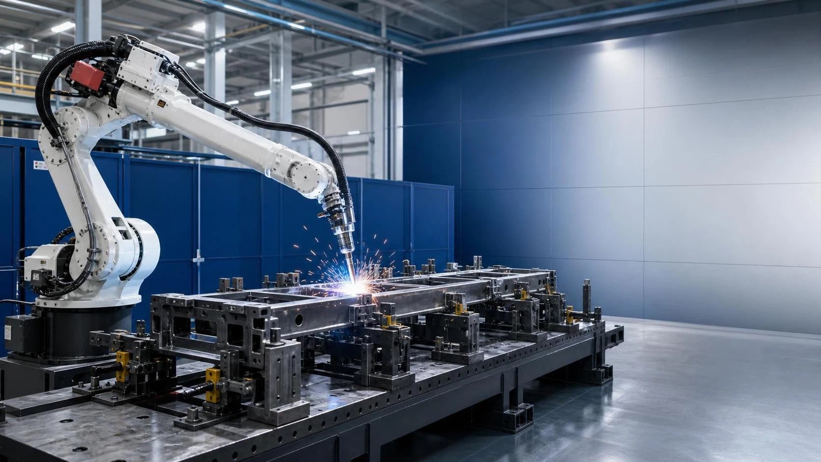
Does a 2000mm Reach Welding Robot Reduce Fixture Repositioning?
In many fabrication cells, welding itself is not the largest source of lost time. The repeated stopping, unclamping, rotating, re-locating, and re-checking of a workpiece often consumes more operator attention than the arc-on cycle. A 2000mm reach welding robot can reduce fixture repositioning substantially when it can access multiple weld zones from one stable part location. For long frames, structural members, machine bases, large brackets, and multi-sided assemblies, that additional working envelope may eliminate one or more manual interventions per part.
The important qualification is that reach alone does not guarantee fewer changeovers. A robot may physically reach a joint while still lacking a safe torch angle, adequate clearance for the wrist, or a collision-free path around clamps and part features. Operators evaluating a 2000mm reach welding robot should therefore look beyond the radius shown on a specification sheet. The real question is: can the robot weld the required joints, in the required sequence, while the part remains securely located in a fixture that is practical to load and maintain?
What the 2000mm Reach Changes on the Shop Floor
A robot’s reach is generally measured from its base axis to the center of the wrist flange. It is useful, but it is not the same as usable welding reach. Once a torch, wire feeder package, anti-collision device, neck angle, and workpiece clearances are included, the practical envelope becomes smaller and more complex. Even so, a nominal 2000mm reach gives a robot a meaningful advantage over shorter-arm models when welds are spread across a long assembly.
Consider a fabricated beam or chassis section with welds at both ends, gussets along the side, and internal cross-members. With a short-reach robot, the fixture may need to shift along a linear track, the part may need to be repositioned, or a second station may be required. A longer-reach robot can often cover the length from a fixed base position, allowing the operator to load once, start the cycle, and prepare the next part while welding continues. The gain is not merely fewer movements. It is fewer chances to lose datum accuracy after unclamping and fewer interruptions to the programmed sequence.
This is especially relevant where a fixture holds the assembly square before welding. Every repositioning event introduces a small risk: clamps may be tightened differently, a component may settle against a different stop, spatter may interfere with a locating face, or a hot part may distort enough to make re-clamping less repeatable. A well-designed one-setup process does not remove those risks entirely, but it limits how often they occur.
When a Long-Reach Robot Really Eliminates Repositioning
The strongest results usually appear where the part has a long footprint but modest height and where most seams are visible from one or two sides. Examples include ladder-type frames, H-beam attachments, conveyor structures, agricultural equipment subassemblies, and fabricated machine frames. In these applications, the operator can place the workpiece on a fixed fixture, and the robot can travel between weld zones without requiring the fixture to be moved after each group of seams.
A 2000mm reach welding robot can also reduce the need for duplicated fixtures. Rather than placing separate fixtures within the reach of multiple compact robots, one larger robot may serve a wider fixture or two closely positioned loading zones. That can simplify material flow, though it must be balanced against cycle-time requirements. If one robot becomes the bottleneck, a larger envelope does not automatically improve throughput.
Part consistency matters just as much as size. If incoming cut components vary in length, hole position, or edge condition, the robot may still pause for operator adjustment or require touch sensing and seam tracking. A longer arm cannot compensate for inconsistent fit-up. It only allows the programmed robot and torch to travel farther from one installation point.
The difference between “reachable” and “weldable”
For welding, access must be assessed in six-axis motion, not as a flat circle drawn around the robot base. The wrist needs room to orient the torch correctly. Cable routing must not snag on clamps. The nozzle requires clearance from walls, webs, stiffeners, and adjacent components. A fillet weld near the inside corner of a deep fabrication may be technically within the robot’s radius but impossible to complete at the correct work angle.
This is why layout reviews should include actual torch geometry and at least representative fixture components. A cell simulation is valuable when available, but an experienced integrator can also identify many conflicts from part drawings, weld maps, fixture concepts, and a clear definition of the loading method. Operators should be invited into that review. They often know where lifting equipment, tack weld variation, part handling, and cleanout access will affect the cell long before commissioning begins.
Fixture Design Still Determines the Outcome
A long-reach robot is most effective when the fixture supports its movement rather than blocking it. The fixture should establish repeatable primary datums, hold the workpiece against welding distortion, and leave the torch sufficient approach space. Overbuilt fixtures sometimes solve one problem while creating another: heavy plates, tall supports, and clamps positioned directly beside seams can force the robot into poor angles or make portions of the part inaccessible.
Where possible, keep locating features below the weld plane or outside the torch’s approach path. Use clamps that can be retracted if they obstruct travel, but do not trade clamping rigidity for access without checking distortion behavior. For assemblies that require welding on several faces, a positioner may be more useful than additional robot reach. Turning the part into a favorable welding position can improve bead consistency, reduce overhead or vertical-up welding, and make inspection easier.
The choice is rarely “fixed fixture versus positioner” in absolute terms. A fixed fixture and 2000mm reach welding robot may be ideal for long, mostly one-sided products. A headstock-tailstock positioner, L-positioner, or other rotating arrangement may be better for parts with continuous welds around multiple sides. Some larger cells combine both approaches: the robot spans the workstation while the fixture rotates only when orientation—not distance—is the limiting factor.
Do Not Select by Reach Without Checking Payload and Cycle Dynamics
Long-arm robots are not interchangeable. The torch package, reamer requirements, wire conduit, collision sensor, and dress-out arrangement all add practical demands. Payload capacity must cover the end-of-arm equipment with a suitable margin, and the robot should maintain stable, repeatable movement over the programmed path. A cell that reaches every seam but has awkward cable dress, frequent near-singularity positions, or excessive joint travel may prove difficult to keep running smoothly.
The base position deserves equal attention. Moving the robot base slightly closer to the actual seam pattern can sometimes deliver better access than selecting an even longer arm. Conversely, placing a 2000mm robot too close to the fixture may create folded wrist positions near the center of the cell. The most usable zone is not always at maximum extension or immediately beside the base. Layout should be planned around the full seam map, not the outside dimensions of the part alone.
Weld sequencing also changes the repositioning calculation. A robot can travel to every seam, yet the process may still require a part turn because of heat input, distortion control, interpass cleaning, or the desired welding position. Discuss sequence early: tack locations, opposing weld order, stitch patterns, and the point at which the operator must inspect or remove spatter can all affect whether a single setup is realistic.
Upstream Cutting Accuracy Has a Direct Effect on Robot Availability
Fixture repositioning is often discussed as a welding-cell issue, but it begins upstream. If laser-cut or CNC-cut parts arrive with consistent dimensions and clean edges, locating pins and stops work as intended, joint gaps are more predictable, and robotic programming becomes easier to repeat. If parts vary, operators may compensate by shimming, pushing, grinding, or changing clamp pressure—activities that consume the time a larger robot was expected to save.
For structural fabrication that combines profile preparation and robotic welding, equipment such as an H beam cnc fiber laser cutting machine can be relevant to the overall process plan. Its stated positioning accuracy of ±0.01mm and repeat positioning accuracy of ±0.03mm describe cutting-machine capability, not guaranteed finished assembly accuracy. Actual fit-up still depends on material condition, nesting, handling, bending or rolling operations, and fixture control. But accurate CNC preparation can reduce avoidable variation before the work reaches the welding cell.
This connection is useful for operators because it changes troubleshooting. When a robot repeatedly misses a joint or requires frequent touch-up, the cause may not be robot programming. Check the part datum, cut edge, component squareness, tack sequence, and fixture wear before changing the path. A robust robotic process is built from consistent inputs.
A Practical Selection Review Before Committing
Before selecting a 2000mm reach welding robot, collect more than a general part drawing. Provide the largest and smallest product variants, a weld schedule identifying joint type and required positions, estimated component weights, material thicknesses, expected production mix, and a simple view of how parts are loaded and unloaded. Mark the seams that currently force operators to reposition fixtures. Those are the locations the proposed cell must prove it can handle.
Ask for confirmation of practical access rather than a broad statement that the robot “covers the workpiece.” Useful questions include whether the quoted reach includes the intended torch and anti-collision device, which seams need a positioner, where the robot is closest to joint limits, how the cable package is protected, and how operators safely enter the cell for loading, maintenance, and recovery. Safety guarding, interlocks, extraction, and applicable electrical or machinery requirements must be finalized for the actual installation and destination market.
Wuxi Samgins International Trade Co., Ltd., established in 2012 in Wuxi, Jiangsu Province, works across automatic welding equipment, CNC cutting machines, machine tools, H-beam production equipment, and sheet-metal processing machinery. That broader process view is useful when a robot cell must match upstream cutting and downstream fabrication rather than operate as an isolated purchase. The company organizes production and design in line with ISO9001 quality-system practices and EU CE standards, while final compliance requirements should always be confirmed against the machine configuration and local installation conditions.
The Decision in Plain Terms
Yes, a 2000mm reach welding robot can materially reduce fixture repositioning when the main limitation is the distance between weld zones on a stable, well-fixtured assembly. It is particularly compelling for long fabricated products where manual relocation breaks flow and risks changing the part datum. It is less decisive when joints are hidden, multi-sided, poorly presented to the torch, or dependent on frequent part rotation.
The best decision comes from reviewing the complete path: cut-part variation, fixture access, robot posture, torch geometry, weld sequence, positioner needs, and operator loading routine. If those elements support a one-setup strategy, the additional reach becomes a practical productivity tool rather than simply a larger number in the robot specification.
search
Products Navigation
Send Us A Message