




How to verify whether an 1800mm reach welding robot fits your cell
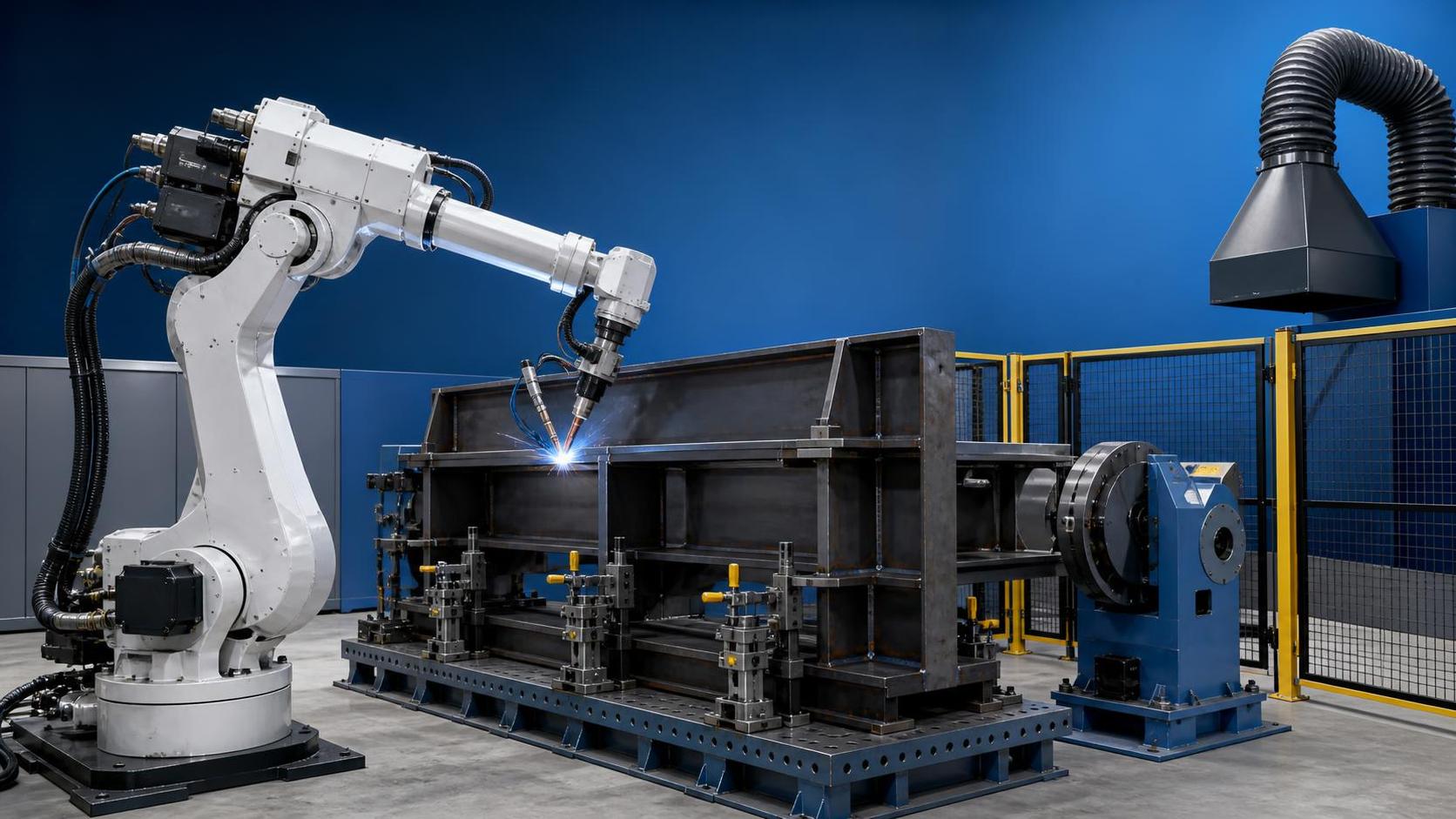
An 1800mm reach welding robot may look suitable on a supplier’s specification sheet, yet nominal reach alone does not prove it will weld every required joint in your cell. The real question is whether the robot can approach each seam with a usable wrist angle, clear the fixture and part, maintain stable torch orientation, and still leave room for safe loading, maintenance, and future product variation.
A reach figure describes the maximum distance from the robot base to the wrist center under a favorable pose. It does not describe the complete usable welding envelope. A robot can technically reach a point and still be unable to produce an acceptable weld there because an axis is near its limit, the torch collides with a clamp, the cable package twists too tightly, or the required welding angle cannot be maintained.
That distinction should guide the whole evaluation. Do not begin by asking whether 1800 mm is enough for the longest dimension of the workpiece. Begin with the welding points, their required approach directions, and the physical obstacles around them.
Start with the real welding envelope, not the robot reach circle
Many early layouts show a simple circle around the robot base. That circle is useful only as a rough first filter. Welding cells are three-dimensional. A long horizontal reach may be available, while the same point becomes difficult when it is high, low, behind a vertical plate, or close to the robot pedestal.
Build a list of every weld family before reviewing robot models. Include seam length, part location, welding position, torch angle, root access, joint type, and whether the part must be welded on more than one side. A simple fillet weld along the outside of a frame has very different access requirements from a groove weld inside a box section.
The most useful question is: can the torch reach the seam while the last robot axis still has enough freedom to orient and travel smoothly? A pose that reaches the seam only at a wrist limit is usually not a production-ready pose. It may work during a demonstration, then become unstable when workpiece tolerances, spatter buildup, or a slightly different fixture position are introduced.
A practical assessment should model or measure the following:
- Robot base position, pedestal height, and anchor footprint.
- Largest and smallest workpiece dimensions, including realistic manufacturing tolerances.
- Fixture body, clamps, locating pins, work supports, and cable-routing brackets.
- Welding torch geometry, neck angle, contact-tip extension, and collision sensor length.
- Required torch work angle and travel angle for each critical joint.
- Parts that are presented in multiple positions or require turning equipment.
Do not exclude “temporary” items from this review. Ground clamps, part-present sensors, anti-spatter spray nozzles, wire feeders, torch cleaners, and fume extraction hoods often become the real interference points after installation.
How to verify an 1800mm reach welding robot in the proposed cell
The strongest method is offline simulation using the intended robot model, torch, fixture, positioner, and safety equipment. A simplified CAD study is still far better than estimating from a brochure. It should test the actual path, not only a few static poses at the start and end of a seam.
Where a full simulation is not available, make a physical reach study. Mark the planned robot base on the floor, establish the fixture datum, and use a rigid mock-up or dimensional arm to check the critical points. This will not replace robot kinematics, but it quickly exposes layout assumptions that are too optimistic.
Pay particular attention to the seams that are hardest to access, rather than the seams that occupy most of the cycle time. Typical problem areas include the back side of stiffeners, lower seams near fixture beams, joints beneath overhanging flanges, and corners where two plates restrict torch approach. A cell is only as capable as its least accessible weld.
A direct answer is useful here: an 1800 mm model fits the cell only when every required seam is reachable with collision clearance, acceptable joint orientation, manageable axis posture, and enough reserve for normal part variation. Reaching a nominal coordinate is not sufficient evidence.
Check the robot’s “comfortable” working zone
Every six-axis robot has postures that are mechanically possible but poor for repetitive welding. Near full extension, small changes in part position can create larger positional effects at the torch. Near folded positions, adjacent links may interfere with fixtures or the robot itself. Wrist-axis rotation can also become excessive on long continuous paths, especially around circular or three-dimensional seams.
Ask the robot supplier or integrator to demonstrate axis values throughout the programmed path. The review should identify near-limit joints, wrist singularity risks, abrupt axis reversals, and areas where speed must be reduced. A cycle-time result is meaningful only when it includes acceleration, deceleration, weld starts and stops, search routines, cleaning cycles, and safe movement between joints.
A larger robot is not automatically the answer. Oversizing can increase cost, occupy more floor space, and reduce agility on compact assemblies. But selecting a robot with no working reserve is equally expensive when a fixture must later be redesigned or a second robot is added to cover a missed seam.
Fixture clearance is usually the deciding factor
Fixtures are designed to locate parts rigidly, but robotic welding needs more than rigidity. The torch, wrist, elbow, and dress package must all move through the space around the joint. A clamp placed 80 mm from a weld may be fine for manual welding and impossible for a robotic torch with a collision sensor.
Review fixtures with both manufacturing and welding personnel involved. The fixture designer may optimize clamping force and loading access; the welding programmer sees the required torch approach and exit path. Neither viewpoint alone is enough.
Good fixture design generally puts clamps away from the weld path, provides deliberate clearance around critical corners, and uses locating features that do not force the torch into a narrow channel. It also considers repeatability. If a part can shift within its locating tolerance, the programmed path needs enough clearance to absorb that shift without touching a clamp or losing the weld joint.
For H-beams, box beams, columns, and other structural fabrications, upstream fit-up quality affects this decision more than many buyers expect. An end face that is not flat or square can change the joint gap and move the weld line from part to part. In applications where beam ends are prepared before robotic welding, a CNC end-processing machine such as the Standard NC Face milling machine can support more consistent fit-up by machining accurate end faces. That does not eliminate the need for seam tracking or tolerant fixturing, but it reduces one avoidable source of variation.
Do not ignore torch access and process hardware
The robot arm does not weld; the complete welding package does. A torch with a long neck, gas cup, collision device, and wire conduit can reduce accessible space substantially. The same applies to tandem torches, narrow-gap equipment, laser-hybrid heads, or large integrated sensors.
Request the supplier’s accurate CAD model for the complete end-of-arm tooling. A generic flange model is inadequate. Check all planned torch necks, because a neck selected later to improve one difficult joint can create interference elsewhere.
Also consider cable routing over the entire motion range. Dress packs can snag on fixture corners, rub against positioners, or limit wrist rotation long before the robot reaches a software axis limit. In production, poor cable management often appears first as erratic wire feeding, damaged conduit, or unplanned downtime rather than an obvious collision alarm.
For parts with deep internal seams or many hidden welds, an 1800 mm reach welding robot may not be the most effective arrangement even if the arm can reach the opening. A headstock-tailstock positioner, a tilt-and-rotate fixture, a rail-mounted robot, or a different part presentation may produce a much more stable process. Repositioning the workpiece is often cheaper than forcing the robot to work at an unfavorable angle.
Base location, positioners, and part movement
Robot base placement is a high-leverage decision. Moving the base a few hundred millimeters can improve access to one side while making another side unreachable. Raising the robot on a pedestal can help with upper seams, but it may worsen lower seams and increase the required safety envelope.
When a positioner is included, evaluate the robot and positioner as one coordinated system. Rotation can bring seams into a favorable flat or horizontal-vertical welding position, shorten robot travel, and reduce the need for difficult overhead welding. It can also create new collision risks between the robot, tooling, workpiece, and safety fence.
Do not approve the layout from a single parked position. Simulate loading, clamping, positioner rotation, welding, torch cleaning, wire change, manual recovery, and maintenance access. A cell that produces a good weld but cannot be safely serviced is not a complete solution.
Safety space and access after installation
Reach verification must include the guarded envelope, not just the work envelope. The safety fence, gates, light curtains, interlocks, and material loading route can constrain the final base location. Local risk assessment requirements and the applicable machinery safety standards should be confirmed for the destination market rather than assumed from an initial layout.
Leave practical access to the power source, wire drum, torch cleaning station, control cabinet, and fixture wear parts. Maintenance teams need space to inspect cables, replace contact tips, clear spatter, and recover from a fault. If those tasks require entering a narrow guarded zone or moving equipment, availability will suffer.
Wuxi Samgins International Trade Co.,Ltd supplies welding automation and structural fabrication equipment alongside CNC cutting, machining, and H-beam production solutions. For combined fabrication projects, that broader equipment view is useful because robot reach, part preparation, fixture strategy, and material flow should be checked together instead of purchased as isolated machines.
A final approval checklist
Before releasing a purchase order, ask for evidence rather than broad confirmation that the robot “covers the part.” The supplier or integrator should provide a layout drawing, reach or simulation study for all critical welds, collision review, projected cycle time, fixture concept, torch and cable-package details, and a clear list of assumptions. Those assumptions matter. If the study assumes perfectly straight parts, fixed torch geometry, or no future product variation, record that limitation.
It is also sensible to define acceptance criteria early: which parts will be run, which joints will be inspected, what welding positions are permitted, how repeatability will be checked, and which cycle-time conditions apply. This prevents a later disagreement where the robot technically performs a path but does not meet the intended production requirement.
An 1800mm reach welding robot is often a practical size for medium-to-large fabricated assemblies, but it should be selected from verified cell geometry and process access, not from reach alone. The right decision is the one that leaves usable motion reserve, protects weld quality, and gives the operation room to handle real parts rather than ideal CAD models.
FAQ
Is 1800 mm reach measured to the torch tip?
Usually, the published figure refers to the robot’s wrist center or flange reference point, depending on the manufacturer’s definition. The effective torch-tip reach changes with the torch, collision sensor, mounting angle, and cable package. Confirm the manufacturer’s measurement convention before comparing models.
How much reach margin should a welding cell have?
There is no universal percentage. The required margin depends on part variation, fixture tolerance, torch geometry, and future product changes. The important point is that critical seams should not depend on full extension, axis limits, or a near-collision posture.
Can offline simulation replace a physical trial?
No. Simulation is the best early validation tool, but a physical trial remains valuable for checking arc stability, spatter, real part variation, cable behavior, and loading ergonomics. Use simulation to prevent layout mistakes, then validate the process with representative parts.
When should a rail-mounted robot be considered?
Consider a rail when workpieces are long, multiple stations must be served, or a fixed-base robot would spend much of its cycle near maximum extension. A rail adds controls, guarding, and maintenance requirements, so it should solve a clear coverage or throughput problem.
Internal Link Anchor Text Suggestions
- Robot welding cell layout planning: welding automation design guide
- Welding positioner selection: turning and rotating fixtures for robotic welding
- H-beam production line equipment: structural steel fabrication solutions
- CNC face milling for beam end preparation: fit-up and alignment equipment
- Robotic welding torch accessories: collision sensors and torch cleaning stations
External Reference Directions
- Robot manufacturer official technical manuals and reach-envelope documentation.
- Applicable machinery safety guidance from recognized standards bodies and local regulatory authorities.
- Professional welding association resources on robotic welding procedure qualification, fixture design, and weld quality control.
search
Products Navigation
Send Us A Message