




What work envelopes suit a 1500mm reach welding robot?
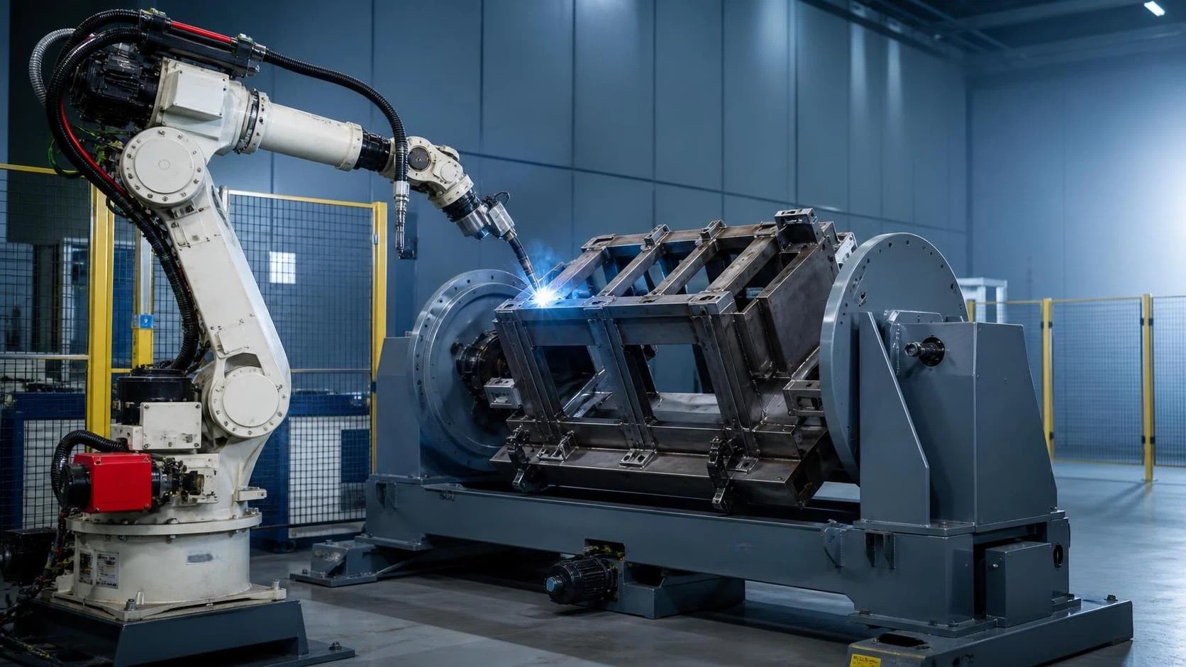
Choosing the right work envelope for a 1500mm reach welding robot is essential for achieving stable weld quality, efficient cycle times, and safe material handling. This guide explains how to assess robot reach, payload, welding position, fixture layout, and cell clearance for common fabrication tasks such as structural steel, frames, pipes, and H-beam components. Learn which workspace dimensions best support your production requirements before selecting a robotic welding solution.
A 1500mm reach welding robot is generally suited to medium-sized fabrication cells rather than very small bench-work stations or long-beam production lines. Its nominal reach places it in a practical range for repetitive welding of fabricated frames, brackets, vehicle subassemblies, agricultural machinery parts, structural steel nodes, cabinets, and moderate-diameter pipe assemblies.
The key point is that a robot’s stated reach is not the same as the usable welding envelope. A “1500mm reach” normally refers to the maximum radial distance from the robot base reference point to the wrist flange under a particular arm posture. In a real welding cell, the torch length, cable package, workpiece geometry, positioner, fixture, collision zones, and required torch angle all reduce or reshape that theoretical area.
For this reason, buyers should not ask only, “Can the robot reach the weld?” The more useful question is: “Can it reach every required weld with the correct torch orientation, clearance, travel continuity, and access for loading and maintenance?”
What a 1500mm reach means in a welding cell
A six-axis robot with approximately 1500mm reach can usually cover a circular or partially circular workspace around its mounting base. Yet the actual accessible volume is irregular. Robots lose access near the base, at high vertical positions, at full extension, and where joint limits prevent the welding torch from maintaining the required angle.
In arc welding, access is especially dependent on orientation. A torch may physically arrive at a joint but still be unable to hold a suitable work angle and travel angle. This is common on inside corners, box-section frames, closely spaced gussets, deep channels, and workpieces mounted against a fixture plate.
As a rough planning concept, a 1500mm robot is often most comfortable when the majority of weld locations sit within a moderate working band rather than at the absolute outer edge of its reach. Designing every weld at maximum extension can cause several problems:
- Reduced stiffness at extended arm positions;
- Less favorable wrist orientation for torch control;
- Higher collision risk between arm, torch, fixture, and workpiece;
- More difficult cable routing;
- Longer robot movements when the robot must retract and reorient between seams;
- Greater sensitivity to dimensional variation in fabricated parts.
A workable cell should allow the robot to approach key seams from more than one posture. That flexibility matters when fit-up changes, weld spatter accumulates on fixtures, or a revised product design introduces a gusset, flange, or service hole that narrows access.
Workpiece sizes commonly suited to this reach range
For flat or open fabricated assemblies, a 1500mm reach robot can often handle workpieces with an overall length or width exceeding 1500mm, provided the robot is placed intelligently and the part is rotated or repositioned during the cycle. The robot does not need to cover the entire product from one fixed viewpoint.
For example, a rectangular machinery frame measuring around 2000mm by 1000mm may be within range if it is mounted on a single-axis or two-axis positioner. The positioner can present each side of the frame to the robot, keeping the weld zones in a favorable central portion of the robot’s envelope. Without a positioner, the same frame may require two robot stations, manual repositioning, or a robot on a track.
Typical applications include:
- Structural brackets and fabricated supports: Small to medium assemblies with fillet welds, gussets, plates, and stiffeners.
- Equipment frames: Pump skids, generator frames, machine bases, lifting attachments, and enclosure structures.
- Automotive and transport components: Trailer parts, axle supports, chassis subassemblies, racks, and formed steel structures.
- Agricultural machinery: Implements, mounting frames, loader attachments, and repetitive fabricated components.
- Pipe and tube fabrications: Manifolds, supports, branch connections, and pipe-to-plate assemblies where a rotator or positioner is available.
- Moderate structural steel members: Connection plates, short columns, stiffened beams, and fabricated nodes.
Long products are a different case. A 1500mm reach robot can weld sections of a long H-beam, box beam, or plate girder, but it cannot economically cover many meters of longitudinal weld from a stationary base. Those applications normally call for a gantry system, a travelling carriage, a robot mounted on a linear track, or a dedicated H-beam welding line. The robot may still be valuable for end details, stiffeners, diaphragms, cope areas, and complex attachment welds that a dedicated longitudinal welding machine cannot easily handle.
The importance of part presentation
Most unsuccessful robotic welding layouts are not caused by insufficient robot reach alone. They result from treating the workpiece fixture as an afterthought. A fixture determines where the part sits, how repeatably it is located, whether clamps obstruct the torch, and whether the robot can access both sides of a joint.
A fixed horizontal table is suitable for simple, open workpieces with welds mostly on the top surface or outer faces. It becomes restrictive when the part has underside welds, internal seams, or multiple sides that require downhand welding. In those cases, a positioner is often a more effective investment than selecting a larger robot.
Rotating the workpiece can convert difficult vertical-up, overhead, or horizontal welding paths into downhand positions. This improves weld consistency, helps control molten pool behavior, and often raises deposition efficiency. It also allows the robot to use simpler, faster motions instead of repeatedly changing wrist posture.
For a 1500mm reach welding robot, common cell arrangements include:
- Robot beside a single-axis headstock-tailstock positioner: Suitable for frames, shafts, tubular assemblies, and parts that need rotation around one axis.
- Robot facing an L-type or two-axis positioner: Useful for box structures, frames, and assemblies requiring access to several faces.
- Robot between two loading stations: A dual-station layout supports loading on one side while welding continues on the other, provided safety separation and part weight are properly considered.
- Robot mounted beside a fixed jig: Appropriate for high-volume, low-complexity assemblies with dependable access from one direction.
The distance between robot base and fixture center cannot be selected using reach alone. If the fixture is too close, the arm may enter a difficult folded posture or collide with the positioner. If it is too far away, outer welds may only be reachable at near-maximum extension. Offline simulation or supplier-generated reach studies are particularly useful before equipment is ordered.
Vertical reach and height differences are often underestimated
Fabricators frequently focus on horizontal dimensions while overlooking height. A welding robot may need to reach the top of a tall frame, the far side of a beam, or a seam elevated by a fixture or positioner. The effective vertical reach depends on the robot’s shoulder configuration, wrist angle, and the orientation of the installed torch.
A workpiece that is 1200mm high may appear compatible with a 1500mm reach robot on paper, but the upper seams could become difficult if the robot is floor-mounted close to the part. Raising the robot on a pedestal can improve access to elevated joints, although it may reduce access to low-level seams near the fixture base. Conversely, mounting the robot low can favor plate and frame fabrication but may create interference around tall assemblies.
Overhead, side, and elevated installation options can help solve particular access problems, but they should be evaluated carefully. They affect cable routing, maintenance access, safety guarding, and the overall stiffness of the mounting arrangement. The mounting structure must be engineered for the robot’s dynamic loads, not just its static weight.
Payload is about more than the welding torch
For welding applications, payload should include the torch, neck, wire feeder or integrated feeder components, dress pack, torch cleaning allowance, sensors, seam-tracking equipment, and any future additions. A robot selected with minimal spare payload may be adequate for a basic MIG/MAG torch but become unsuitable when laser seam tracking, through-arc sensing hardware, collision detection, or a heavier torch configuration is added later.
Payload also affects speed and motion stability. Even where the robot can carry the equipment, rapid changes in direction with a heavy wrist load can limit cycle performance. A supplier’s payload figure must be interpreted together with allowable wrist moments and inertia values, particularly for long torch assemblies.
One reference point is the Multipurpose Handing Robot BR20iB-18, a six-axis model specified with a 20kg payload, ±0.08mm repeatability, and 1911mm maximum reach. Its reach is larger than the 1500mm class discussed here, illustrating why nominal reach should be compared against the complete cell layout rather than used as an isolated purchasing criterion. A longer-reach machine may offer more flexibility for fixtures or larger assemblies, but it does not automatically deliver better access in confined work.
Repeatability matters, but fit-up still controls weld quality
Robot repeatability is important because the robot must return to programmed positions consistently. However, repeatability should not be confused with absolute accuracy or with finished weld quality. A robot can repeat a path very precisely while welding the wrong location if the part is not consistently positioned, the fixture has worn, or incoming components vary in dimension.
This distinction is central in general steel fabrication. Processes such as plasma cutting, manual tack welding, thermal distortion, bending variation, and inconsistent hole location can create part-to-part changes that exceed the acceptable range of a fixed robot program. If these variations are significant, the cell may need robust locating features, improved upstream process control, touch sensing, through-arc seam tracking, laser vision, or adaptive programming.
For simple repeat products, a basic fixture and well-maintained locating pins may be sufficient. For variable fabricated assemblies, the cost and complexity of seam sensing should be considered early. It is much harder to add after a cell has been designed around tight clearances and inaccessible sensing paths.
How much clearance should the cell have?
The working envelope is only one part of the required floor area. A robotic welding cell also needs room for guarding, part loading, electrical cabinets, welding power source, wire drums, fume extraction, torch cleaning equipment, maintenance access, and safe operator movement.
There is no universal cell footprint for every 1500mm reach robot because it depends on fixture size, part handling method, and safety concept. Nevertheless, a common planning mistake is to draw the robot’s maximum reach circle and assume that the cell boundary can sit just outside it. In practice, the guard perimeter must account for the robot’s full range of motion, possible dropped or displaced parts, moving positioners, the torch and cable package, and the safe loading area.
Where external axes are involved, risk assessment becomes even more important. A rotating positioner can create pinch points, crush hazards, and unexpected sweep zones beyond the robot’s own motion envelope. Safety fencing, interlocked doors, light curtains, scanning devices, and safe speed functions should be selected according to the actual operation and applicable local requirements. In export projects, the responsible integrator should confirm which machinery safety regulations and conformity procedures apply in the destination market rather than assuming that one documentation set covers every jurisdiction.
When 1500mm is too small—and when it is unnecessarily large
A 1500mm reach may be too small when a single fixed robot must weld both ends of a large frame, access around deep structural members, reach across a wide fixture, or service several stations without part repositioning. It can also be limiting where the weld is located inside a large enclosure or at the far side of a bulky workpiece.
In such cases, options include a longer-reach robot, a linear rail, a repositioning system, or redesign of the fixture. The lowest-cost answer is not always the robot with the longest arm. A compact robot paired with an appropriately sized positioner can sometimes produce a better welding posture and shorter cycle time than a large robot working around a fixed table.
At the other extreme, an oversized robot may be inefficient for compact parts. Larger arms need more clearance, can complicate safeguarding, and may be less agile in dense fixture environments. For small repetitive parts, a shorter-reach robot can provide a more compact cell and reduce non-welding travel. The right size is the one that keeps most programmed welds in a favorable area of the envelope while leaving enough margin for variation, maintenance, and future product changes.
A practical way to assess a proposed robot envelope
Before selecting a welding robot, prepare a representative part set rather than showing only the simplest component. Include the largest part, the tallest part, the most complex joint, the heaviest torch configuration, and any likely future variant. For each part, identify weld type, seam length, required position, access side, tolerance condition, expected annual volume, and loading method.
Then ask the supplier or system integrator to demonstrate more than a reach circle. A useful study should show the robot base position, fixture and positioner dimensions, torch orientation at each critical seam, collision checks, cable interference risks, and the proposed loading sequence. It should also indicate which welds require part rotation, whether external axes are coordinated with robot motion, and where manual intervention remains necessary.
For a 1500mm reach welding robot, the most suitable work envelope is rarely defined by one maximum product dimension. It is defined by the relationship between the robot, the fixture, the weld locations, and the way the part is presented. Medium-sized fabricated products with repeatable geometry and well-planned rotation are usually a strong fit. Large beams, long seams, enclosed structures, and highly variable assemblies require a broader evaluation of automation architecture before a robot size is chosen.
search
Products Navigation
Send Us A Message