




When six-axis motion matters for complex weld paths
When Six-Axis Motion Matters for Complex Weld Paths
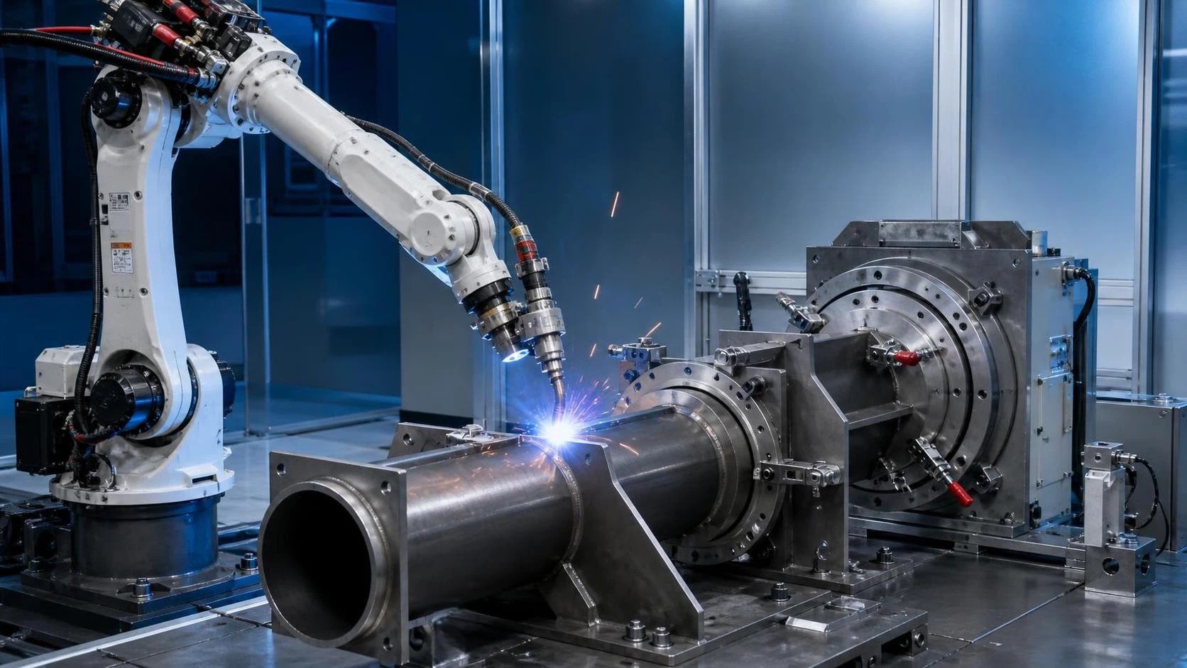
For technical evaluators assessing automated welding for curved, angled, or multi-plane joints, a 6 axis welding robot can determine whether a cell is merely workable or genuinely production-ready.
Its added freedom of movement helps maintain torch angle, reach restricted areas, and support consistent weld quality across complex paths. This article explains where six-axis motion creates measurable manufacturing value.
Start With the Weld Path, Not the Robot Axis Count
Six-axis capability matters when the welding torch must change both position and orientation while following a seam. The evaluation should begin with actual joint geometry, fixture access, and process requirements.
A simple straight seam on an open flat plate may not require extensive orientation control. In that case, fewer robot axes, a positioner, or a dedicated welding carriage may deliver acceptable results.
Complex fabrication is different. Curved seams, intersecting members, deep channels, tubular structures, and multi-face assemblies often require the torch to rotate continuously while maintaining a stable work angle.
The practical question is not whether six axes are technically impressive. It is whether the robot can preserve the specified travel angle, work angle, stick-out, and clearance throughout the complete programmed path.
When those conditions change substantially along a joint, a 6 axis welding robot becomes a process-control tool rather than simply a material-handling device with a welding torch attached.
Evaluators should request representative part drawings, weld symbols, fixture concepts, and access constraints before comparing robots. Axis count alone cannot demonstrate that a specific cell will achieve the required weld profile.
It is also important to distinguish robot motion from coordinated external-axis motion. A two-axis positioner can improve access, but it cannot always replace the wrist orientation flexibility needed around local obstacles.
The best evaluation method is to simulate or physically demonstrate the most difficult seams first. If the robot can manage those joints without awkward posture changes, easier welds are usually straightforward.
Why Torch Orientation Determines Weld Quality
Robotic welding repeatability has value only when the torch reaches the joint in a usable orientation. An accurately repeated but poorly angled torch can still produce inconsistent penetration, bead shape, and spatter levels.
For MIG welding, travel angle affects how the arc interacts with the molten pool. Work angle affects heat distribution between joint members, especially on fillet welds and unequal-thickness assemblies.
On a straight external corner, the torch may remain close to one posture. On a curved corner or changing fillet line, it often needs controlled wrist rotation to avoid losing preferred geometry.
Six-axis motion allows the arm and wrist to divide the movement. The robot can maintain a relatively stable torch attitude while its larger joints reposition the end effector through the work envelope.
This separation is particularly valuable near transitions. A weld may move from horizontal to vertical, pass around a radius, or continue into an area where the torch approach direction changes sharply.
Without sufficient orientation freedom, programmers may accept compromised torch angles or break one intended continuous weld into separate operations. Both choices can increase process variation and cycle time.
Consistent posture also supports stable arc-start and arc-stop conditions. These locations frequently become quality concerns when access is restricted, components vary slightly, or welding parameters must be tightly controlled.
Technical evaluation should therefore compare orientation capability over the complete seam, not only the robot's ability to touch a few programmed points. Continuous-path posture is the meaningful criterion.
Complex Joint Types That Commonly Need Six Axes
Structural steel fabrication provides many examples. Stiffeners, gussets, box sections, beams, frames, and brackets can combine multiple welding planes within a compact assembly and create difficult approach angles.
Tubular and round-section components are another common case. Circumferential seams, saddle joints, and pipe-to-plate connections require coordinated position and orientation changes as the weld progresses around the component.
Machinery frames often contain internal corners and cross-members. The torch must clear surrounding material while retaining a useful angle, particularly where fixtures prevent the part from being freely repositioned.
Vehicle subassemblies may include thin-gauge brackets, formed panels, and access-sensitive joints. Here, consistent torch orientation helps control heat input while robotic repetition supports appearance and dimensional consistency.
Metal cabinets and fabricated enclosures can also benefit where seams turn around corners or continue across formed features. The robot may need to approach from several directions within one controlled cell.
Multi-pass welding introduces another reason to evaluate six-axis motion carefully. Each pass may need a similar path but a slightly different offset, torch angle, or travel direction to manage weld buildup.
Parts with varying joint depth deserve particular attention. A torch that can reach the seam centerline may still collide with sidewalls, clamps, or the workpiece when it attempts to maintain suitable orientation.
These conditions do not automatically require the largest robot. They require an appropriate combination of reach, wrist articulation, payload, fixture design, and programmed path strategy.
Reach and Wrist Motion Must Work Together
A robot with generous reach can access a large fixture, but reach alone does not guarantee useful welding access. The wrist must retain enough articulation near the actual joint location.
This is why technical evaluators should review reach diagrams rather than relying only on maximum reach figures. Robot postures near envelope limits can restrict speed, orientation, clearance, or singularity avoidance.
For medium-to-large fabricated parts, the 6 Axis 2000mm ArmSpan MlG Industrial Welding Robot provides a maximum working radius of 2127 mm for broad fixture coverage.
Its 6 kg payload is intended for a welding torch and related end-of-arm equipment. Evaluators should still include torch body, wire package support, sensors, dress-out hardware, and any seam-tracking equipment.
Wrist-axis speed is relevant where the path contains frequent changes in direction. Fast wrist movement can reduce non-welding repositioning time and help preserve a smoother programmed torch orientation.
However, the fastest theoretical axis speed is not the same as weld speed. During welding, motion must comply with arc stability, heat-input limits, wire-feed behavior, and required bead geometry.
Robot reach should also be considered against cell layout. A long-reach robot may cover multiple stations, while a smaller model may provide better stiffness or access in a tightly constrained enclosure.
Evaluate the full working envelope with actual fixtures, not only bare parts. Clamps, ground connections, fume extraction, safety fencing, cable routing, and part loading space all affect useful robot access.
Repeatability Is Important, but It Is Not the Whole Process
Repeatability describes the robot's ability to return to a commanded position. It is essential for repeated production, but it does not compensate for poor part fit-up, fixture drift, or inaccurate seam location.
A published repeatability value of plus or minus 0.08 mm can support consistent robotic positioning for many fabricated steel applications. The achieved weld result still depends on the total system.
That system includes component tolerances, welding torch condition, consumable wear, wire feed stability, shielding gas delivery, welding power source settings, and fixture locating repeatability.
For high-volume production, small variation can accumulate. A joint that shifts relative to its nominal location may change the effective torch angle, contact-tip-to-work distance, and arc behavior.
Technical evaluators should determine whether fixed-path programming is sufficient. If incoming parts vary materially, seam finding, through-arc sensing, laser vision, or adaptive process strategies may be necessary.
Six-axis flexibility can make those corrections easier to apply because the robot has more options to move around the joint. It does not eliminate the need for reliable part presentation.
Ask suppliers to clarify the basis of the repeatability specification and demonstrate it under representative payload, cable routing, and welding conditions. Bare-robot figures alone are incomplete acceptance criteria.
A well-designed fixture is often the most cost-effective quality improvement in a robotic welding project. It establishes the repeatable joint location that lets the robot's motion capability create value.
Cell Design Can Make or Waste Six-Axis Capability
Robot selection and cell design should proceed together. A capable six-axis arm may still have poor access if fixtures force clamps into torch paths or if loading arrangements block useful approach directions.
Ground mounting is common because it simplifies installation and maintenance. Ceiling or wall mounting can be valuable where floor space is limited or where the robot must reach over a fixed process area.
Multiple mounting options can improve layout flexibility, but each option requires detailed analysis of load paths, maintenance access, safety protection, cable routing, and collision-free motion.
Rotating positioners often complement a six-axis robot effectively. They present the workpiece in favorable welding positions, while the robot makes local orientation corrections around individual seams and features.
The goal is not to force the robot to solve every access problem alone. The goal is to create a cell where the part, positioner, and robot produce stable, productive welding conditions.
For long assemblies, consider whether a track-mounted robot, dual station arrangement, or repositionable fixture will produce better utilization. A large work envelope is useful only when cycle flow supports it.
Collision checking must include the torch, wire feeder, hoses, dress package, clamps, positioner, and unfinished workpiece. The wrist can reach a seam while attached equipment still creates interference.
Service access deserves equal consideration. Consumable replacement, torch cleaning, calibration, and fixture adjustment must be possible without creating excessive downtime or unsafe maintenance procedures.
How to Evaluate Cycle Time Without Misleading Assumptions
A six-axis welding robot may reduce cycle time by limiting part handling, reducing reorientation moves, and allowing several seam directions within one fixture setup. Those gains should be measured, not assumed.
Separate arc-on time from non-arc time during analysis. Arc-on time depends primarily on required weld length and travel speed, while non-arc time includes approach, retract, indexing, cleaning, and loading.
Complex paths can create hidden non-arc losses when the robot must unwind its wrist, avoid a singularity, or move conservatively around obstacles. Offline simulation can reveal these effects early.
Compare cycle time at the desired quality level. Increasing robot speed is not meaningful if it causes unstable deposition, insufficient fusion, excessive undercut, or rework that consumes the apparent gain.
Consider the entire production rhythm. A cell may weld quickly but remain limited by manual loading, tack-welding availability, positioner rotation, inspection, or downstream material handling.
Multi-station designs can improve utilization by allowing an operator to load one fixture while the robot welds another. This approach may be more valuable than selecting a faster robot alone.
For contract fabrication businesses, part mix is equally important. Six-axis flexibility can reduce changeover complexity when varied component families share a cell but require different welding orientations.
Request a time study using real part programs whenever possible. It should document weld sequence, assumed travel speed, tack condition, part handling, cleaning intervals, and expected operator involvement.
Environmental Suitability and Integration Details
Industrial welding cells operate in environments containing spatter, dust, heat, electromagnetic interference, and frequent motion. Robot protection and installation conditions should match the realities of the production floor.
An IP65-equivalent protection level can be relevant for demanding fabrication environments, but it does not remove the need for appropriate shielding, cleaning practices, and protection from direct welding spatter.
Ambient operating conditions also matter. Equipment rated for 0 to 45 degrees Celsius and non-condensing humidity conditions should be installed where temperature, ventilation, and moisture remain within specified limits.
Power integration should be reviewed as a cell-level exercise. Robot controller supply, welding power source, fume extraction, positioners, safety equipment, and auxiliary devices all influence facility requirements.
Communication interfaces deserve early attention. The robot must coordinate reliably with welding equipment, safety controllers, positioners, sensors, and material-handling devices through a clearly defined integration architecture.
Quality documentation is also part of technical risk management. Confirm the applicable machine documentation, safety assessment responsibilities, and product requirements for the market where the cell will operate.
For exported equipment, technical teams should verify applicable regional requirements rather than treating general manufacturing standards as automatic proof of complete cell compliance. The integrator's scope must be clear.
Acceptance criteria should include weld coupons, dimensional checks, programmed cycle time, accessibility, safety validation, fault recovery, and documented performance on the customer's representative workpieces.
A Practical Selection Checklist for Technical Evaluators
First, identify the seams that create the greatest risk: restricted fillets, curved joints, circumference welds, transitions between planes, deep internal corners, and joints located near fixture clamps.
Second, define required torch orientation ranges. Record target work angles, travel angles, contact-tip-to-work distance, approach direction, and whether the torch must rotate while maintaining continuous motion.
Third, establish the actual payload and dress package. Include every component carried by the robot rather than comparing only the nominal weight of an uninstalled welding torch.
Fourth, validate reach at every critical point with realistic fixtures and surrounding equipment. Check both access and exit paths, since the robot must safely enter and leave each welding location.
Fifth, evaluate part variation. Determine whether precision fixtures support fixed programs or whether sensing is needed to locate seams, compensate for gaps, and manage variation between incoming assemblies.
Sixth, review maintainability and operating conditions. A robot cell should provide practical access for torch service, consumables, fixture adjustment, fault recovery, cleaning, and scheduled preventive maintenance.
Finally, measure the commercial case using quality, labor, throughput, floor space, changeover, and rework data. The right automation investment solves a defined production constraint with defendable evidence.
Conclusion: Use Six Axes Where Orientation Is a Production Requirement
A 6 axis welding robot matters most when weld paths demand controlled torch orientation across curves, corners, changing planes, restricted access areas, or multiple seams completed within one fixture setup.
For simple, open, straight joints, six-axis flexibility may offer limited incremental value. For complex fabricated parts, it can protect weld quality, reduce handling, improve access, and simplify repeatable automation.
Technical evaluators should base selection on representative paths, fixture reality, torch posture, payload, reach, variation, and cycle evidence. A successful robotic welding cell is designed around the complete process.
The strongest decision is therefore not “six axes versus fewer axes” in isolation. It is whether the available motion creates the stable welding conditions needed to meet quality and production targets.
search
Products Navigation
Send Us A Message