




Gas Cutting Machine Problems: Uneven Edges, Slag, and Slow Cutting
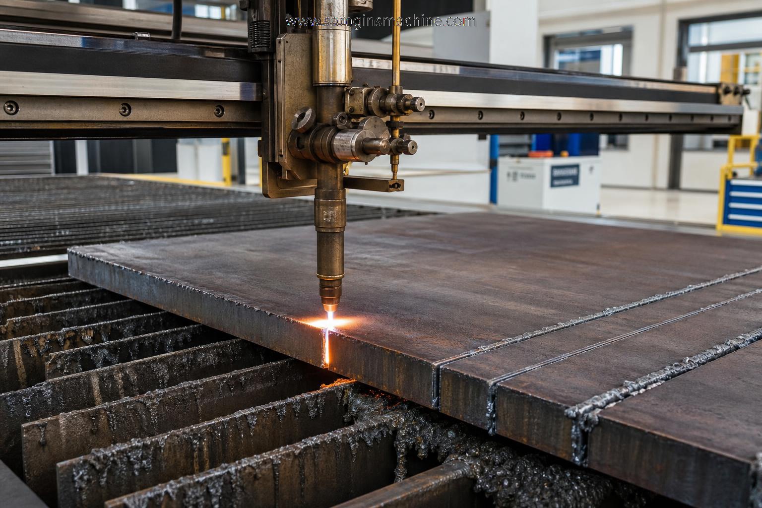
When a Gas Cutting Machine Starts Losing Cut Quality
A gas cutting machine rarely fails in only one way.
Uneven edges, heavy slag, and slow cutting usually appear together.
In metal fabrication, that combination often points to process mismatch rather than a simple machine defect.
Gas purity, nozzle wear, torch height, plate condition, and travel speed all shape the final cut.
The same gas cutting machine can perform well on one job and poorly on another.
That is why troubleshooting should start from the application scene, not from assumptions.
In practical workshops, a thin carbon steel batch, a thick structural plate, and a rusted outdoor stock sheet create very different cutting conditions.
Wuxi Samgins International Trade Co.,Ltd has long worked across cutting, welding, milling, deburring, and forming equipment.
That broader machinery background matters because cut quality problems often continue into later fabrication stages.
A poor edge today can become assembly delay, extra grinding, and dimensional correction tomorrow.
Actual Shop Conditions Change What the Gas Cutting Machine Needs
Different scenes create different priorities.
On repetitive production lines, consistency matters more than peak speed.
On repair work or mixed-batch cutting, flexibility and quick adjustment matter more.
A gas cutting machine used for standard mild steel plates behaves differently from one cutting oxidized stock or recycled material.
Plate flatness also changes results.
If torch height varies across warped sheets, edge quality can collapse even when gas pressure settings look correct.
More commonly, slow cutting is blamed on machine power.
In reality, operators often reduce speed to hide unstable flame behavior or poor preheat.
That protects part completion in the short term, but it increases slag and widens the heat-affected zone.
What usually changes from one job to another
- Material thickness and surface scale
- Required edge condition before welding or machining
- Tolerance expectations for downstream fitting
- Batch size and acceptable rework time
- Gas supply stability and nozzle maintenance level
Thin Plate Jobs Expose Setup Errors Fast
Thin sheet cutting is less forgiving than many expect.
A gas cutting machine on thinner carbon steel can produce rough edges quickly if speed rises faster than preheat stability.
The problem is not always too much speed.
It can also be excessive oxygen flow, which makes the kerf unstable and leaves an irregular lower edge.
This scene usually requires close attention to nozzle size, standoff distance, and ignition consistency.
If the plate carries oil, paint, or light rust, the gas cutting machine may show intermittent drag lines instead of a clean vertical surface.
For thin materials, slight parameter errors become visible immediately.
The best correction is often a smaller step adjustment rather than a full reset of every parameter.
Thick Plate Work Usually Fails for Different Reasons
With thick structural plates, edge problems come from another direction.
Here, a gas cutting machine may look stable at the top cut while failing near the bottom.
That often means the oxygen jet lacks penetration, or travel speed exceeds the material’s oxidation rate.
Heavy slag on the underside is common in this scene.
But slag alone does not prove the cutting speed is too high.
It may also indicate a damaged nozzle or poor gas purity.
Thicker material also raises the cost of wrong settings because every test cut consumes more time and gas.
In this context, keeping a stable gas cutting machine depends on disciplined nozzle inspection and verified gas supply pressure under load.
A practical comparison across common cutting scenes
When Secondary Finishing Becomes the Real Cost
A gas cutting machine should not be judged only by whether it completes the cut.
The more important question is what the edge requires afterward.
In sheet metal fabrication, welded structures, and machined assemblies, post-cut cleanup can consume more labor than the cutting cycle itself.
This is where process linking becomes useful.
If cut parts still carry burrs, slag residues, or dirty inner corners, downstream finishing should be planned early.
For smaller metal parts, irregular profiles, and components with inner holes or threaded areas, Customized Magnetic polishing machine can fit naturally after cutting or machining.
It handles deburring, polishing, cleaning, and grinding in one cycle.
That matters in scenes where manual edge cleanup creates variation between batches.
For precision stampings, CNC parts, die-castings, rail transit components, and electronics hardware, a stable finishing step often protects dimensional consistency better than repeated hand rework.
Different Production Scenes Need Different Judgement Standards
One common mistake is using the same acceptance logic for every job.
That weakens both efficiency and quality control.
A gas cutting machine used for rough blanking can tolerate more edge texture than one feeding direct weld preparation.
Parts intended for visible assemblies may need cleaner surfaces even when dimensional tolerance is moderate.
More delicate sectors also raise the standard.
Aerospace-related components, medical hardware, and high-precision machined parts cannot rely on broad visual judgement alone.
In those cases, cut edge condition should be linked to later deburring and surface treatment capacity.
Where batch finishing is required, models such as R-G110, R-G1610, R-G210, and R-G3010 offer different tank sizes and reference capacities.
That range is useful when production shifts from small precision parts to heavier mixed loads.
Useful judgement points before changing the machine itself
- Check whether the problem appears on one material only
- Compare a new nozzle with the current nozzle under the same settings
- Measure actual gas pressure during cutting, not only at idle state
- Review whether plate contamination is driving unstable preheat
- Estimate total cleanup time created by every poor cut
Misjudgements That Keep a Gas Cutting Machine Performing Poorly
Several problems repeat across workshops.
The first is blaming the gas cutting machine before checking consumables and material condition.
The second is chasing speed while ignoring edge usability.
A faster cut is not more productive if every part needs grinding afterward.
Another frequent error is copying settings from similar-looking jobs.
Plates with similar thickness can react differently because of scale, chemistry, storage condition, or surface coating.
There is also a cost-side blind spot.
Some operations compare machine purchase cost closely, but ignore labor spent on edge correction, nozzle replacement frequency, and scrap from inconsistent starts.
For companies handling complete fabrication lines, this wider view is usually more realistic than judging one machine in isolation.
How to Build a More Stable Cutting Routine
A better routine starts with segmentation.
Group jobs by thickness range, surface condition, and downstream quality demand.
Then create parameter records for each group.
For every gas cutting machine, keep a simple record of nozzle life, cut speed, gas pressure, and common defects.
That approach reduces trial-and-error when similar jobs return.
Where cut parts move into deburring, cleaning, or bright surface finishing, process continuity matters just as much.
For metal workpieces with burr-sensitive edges or hard-to-reach internal areas, the second use of Customized Magnetic polishing machine should be judged by cycle stability, capacity, and whether one operator can supervise multiple units.
Its 3 to 20 minute cycle, forward and reverse translation mode, and no-consumable operation suit many batch finishing scenes.
The point is not to hide poor cutting.
It is to build a cleaner overall fabrication flow.
Before the next adjustment, map the cutting scene, confirm the material condition, and calculate the real cost of rework.
That usually leads to better decisions than changing settings blindly or replacing the gas cutting machine too early.
search
Products Navigation
Send Us A Message