




How to prevent reach-limit faults in a 6 axis welding robot cell
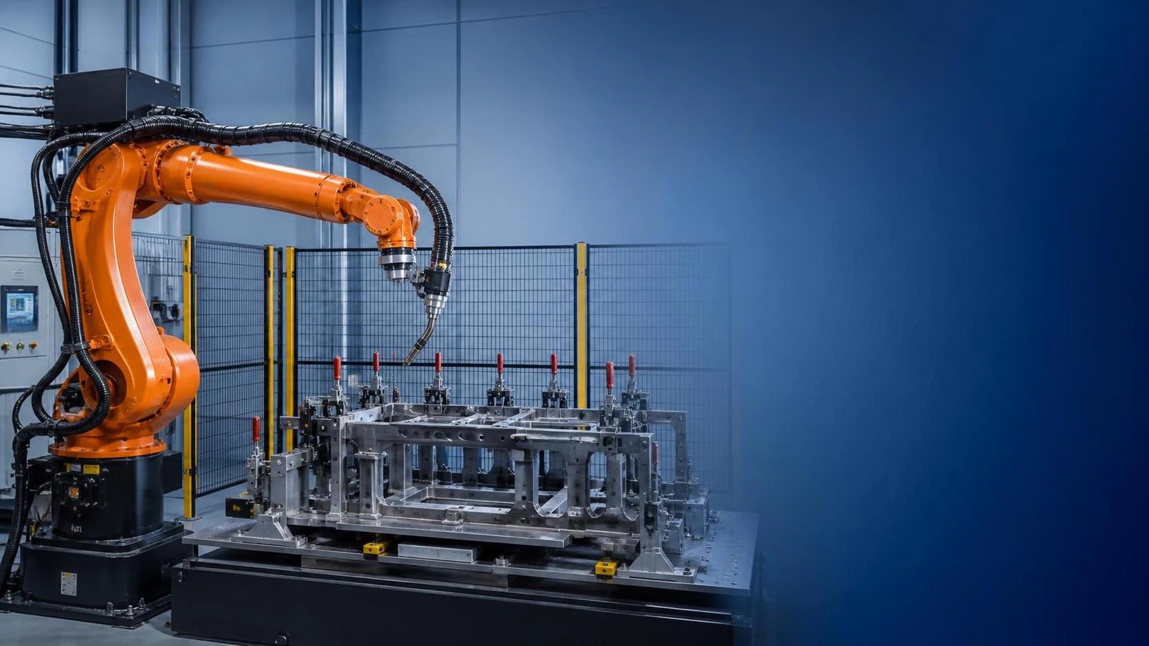
Reach-limit faults can stop production, reduce weld quality, and create unnecessary maintenance costs in a 6 axis welding robot cell. For after-sales maintenance teams, the real challenge is rarely just clearing an alarm. A robot may report an axis overtravel, workspace limit, singularity-related restriction, or collision condition, while the underlying cause sits elsewhere: an offset was changed, a fixture was moved, a torch cable became tight, or a repaired axis was never properly mastered.
Fast recovery matters, but so does preventing the same fault from returning on the next shift. The practical aim is to distinguish between a true mechanical reach problem and a robot that only believes it has reached its limit because its coordinates, tool data, or cell geometry are no longer correct.
What a reach-limit alarm is really telling you
In a 6 axis welding robot, every axis has a permitted travel range defined by mechanical stops, encoder position, controller software limits, and safety settings. A reach-limit fault appears when a commanded movement would take one or more joints beyond an allowed position, or when the programmed TCP path cannot be achieved with a valid joint configuration.
The alarm may occur during manual jogging, automatic cycle start, weld approach, weave motion, or robot return-to-home. Its timing is an important clue. A fault that happens at the same programmed point on every cycle often points to teaching, fixture position, or process changes. A fault that appears at random positions after several hours of production is more likely related to cable drag, loose components, encoder feedback, temperature effects, or gradual mechanical interference.
Do not assume that “axis limit” means the robot arm has physically reached an end stop. Many controllers use soft limits before the hard mechanical limit is reached. That protection is valuable, but it can also hide issues such as lost mastering, incorrect payload settings, or a newly restricted work envelope.
Start with a safe fault investigation
Before moving the robot, record the alarm code, affected axis, operating mode, active program, current tool number, user frame, and approximate robot position. Maintenance teams sometimes lose the most useful evidence by immediately jogging the arm away from the fault location. A short note or controller backup can save hours of repeat diagnosis.
Apply the site lockout and robot cell safety procedure before entering the safeguarded area. Confirm that welding power, wire feed, positioners, external axes, and any automatic clamps are in a safe condition. If recovery requires jogging, use the approved reduced-speed mode and keep clear of pinch points around the wrist, fixture, and workpiece.
Then inspect the physical scene before changing parameters. Look for a torch that has rotated unexpectedly, a bent nozzle contacting the part, a weld spatter buildup on a locator, a displaced workpiece, or a cable bundle caught on a fixture corner. These small changes often consume more robot reach than expected, especially near the limits of axis 4, 5, or 6.
Separate mechanical obstruction from programmed overreach
A useful field method is to ask one simple question: can the robot move through the same area manually, slowly, and without the active weld path?
If it cannot, inspect for a mechanical restriction. Check robot-to-fixture clearance, torch body dimensions, dress pack tension, cable balancer travel, hose routing, and collision damage. Move the arm through the suspected region in joint mode as well as Cartesian mode. Joint mode helps reveal whether a single axis is nearing its travel limit; Cartesian motion may mask that by allowing other joints to compensate.
If the robot can move freely in manual mode but faults in automatic operation, compare the programmed target with the actual production setup. Verify the selected tool center point (TCP), workobject or user frame, and active program version. A tool frame error of only a few millimeters can force the robot into a very different wrist orientation at a difficult approach angle. In a tight welding cell, that difference may be enough to trigger a limit.
Also check whether an operator changed a weld start point, fixture stop, tack sequence, or part orientation to solve a production issue. Such changes may appear harmless on the shop floor, yet they can shift the entire weld path outside the robot’s practical reach envelope.
Axis mastering and calibration deserve special attention
Incorrect mastering is one of the most overlooked causes of repeat reach-limit faults. The controller may show a plausible robot pose even when the actual arm position is offset from the stored encoder reference. This commonly happens after motor replacement, battery failure, encoder work, collision repair, brake service, or an axis component change.
Signs of a mastering issue include:
- The robot reaches a soft limit earlier than it did before maintenance.
- A previously proven program now misses the weld joint or approaches at an unusual angle.
- Home position no longer visually matches the documented reference pose.
- Several taught points are consistently shifted in one direction.
- The fault began immediately after mechanical or electrical service.
Follow the robot manufacturer’s approved mastering procedure rather than “correcting” the problem by editing multiple program points. Check witness marks, calibration pins, mastering gauges, or reference fixtures as applicable. Once the axes are mastered, verify the TCP with a repeatable method and confirm the work frame against the actual fixture datum.
A common but costly shortcut is to alter joint limits or turn off a software boundary to make the alarm disappear. That can turn a recoverable path error into a collision, cable failure, or hard-stop event. Limits should only be changed after confirming that the robot, tooling, and cell safety design support the revised workspace.
Look closely at the welding torch and dress pack
Welding robots are unusually sensitive to changes at the wrist. A torch neck may be bent after a minor collision, an anti-collision device may not reset correctly, or a consumable change may increase the effective tool length. Even when the difference is small, the robot may need a much larger axis 5 or axis 6 rotation to maintain the programmed torch angle.
Inspect the torch mounting, neck alignment, wire feeder connection, liner condition, and cable pack. The dress pack should have enough controlled slack throughout the entire programmed envelope. It should not become taut at maximum reach, rub against sharp fixture edges, or pull the wrist back during a weave cycle. Pay particular attention to the route at the robot upper arm and axis 3 area, where cable movement can look normal at home but become restrictive near an overhead or deep-reach weld.
After replacing a torch, neck, collision sensor, or mounting bracket, validate TCP and weld orientation before releasing the cell. A maintenance team should treat these items as geometric components, not merely consumables.
Fixture drift is often the hidden source of the problem
When the robot reaches a limit only with certain parts, investigate the workholding system. Fixture pins may be worn, clamps may not fully seat, a pneumatic cylinder may have lost stroke, or heat distortion may have altered the resting position of a large fabricated assembly. A few millimeters of variation can be enough to change accessibility in a narrow joint or corner weld.
Check the datum chain from the floor-mounted fixture to the part location. Measure locating pins and stops, inspect clamp faces for spatter, and make sure the part is not being loaded against an obstruction. If a positioner or external axis is involved, verify its zero position and synchronization with the robot program. A robot can appear to have a reach fault when the real error is a rotated positioner that has not returned to its expected angle.
Fixture design also affects the long-term reliability of a 6 axis welding robot. High clamps, deep pockets, and limited torch access can force the arm into singular or near-limit postures. During cell upgrades, consider whether the weld can be approached from a more comfortable robot posture rather than trying to solve every issue in programming.
Program points should be reviewed as a path, not as isolated coordinates
A reach issue is frequently introduced by changing one point to improve another part of the cycle. For example, moving a weld start point closer to a joint may force an aggressive approach move. Adding a weave, changing travel direction, or selecting a different configuration can push the wrist toward an axis limit halfway through the weld.
Review the complete sequence: home position, approach point, weld start, weld path, retract, clearance point, and return motion. Pay attention to configuration changes between points. A robot may reach the same TCP location using different elbow-up or elbow-down solutions, but only one configuration may be safe for the fixture and cable package.
Keep adequate clearance points before and after welding. A direct linear move may look efficient in simulation but leave little room for part variation or torch deflection in production. Where appropriate, use an intermediate joint move to place the robot in a stable posture before beginning a precise linear approach.
Payload and center-of-gravity values should be confirmed as well. Incorrect payload data does not normally create a direct travel limit, but it can affect motion behavior, collision sensitivity, braking, and path stability. On a heavy torch package or with additional seam-tracking equipment, accurate payload settings help keep the programmed motion predictable.
Use upstream preparation to protect robot accessibility
Not every reach problem should be solved at the robot. Poorly prepared joints can force awkward torch angles, extra grinding, rework passes, and prolonged time in constrained areas. For plate fabrication, consistent bevel geometry gives the welding cell a more predictable seam location and access angle.
For example, a Through CNC Milling machine can prepare straight, inclined, U-, V-, or K-type bevels in a controlled pass for carbon steel, stainless steel, and aluminum plates. Depending on the model, it handles thickness ranges from 6–80 mm, with heavy-duty options reaching 6–400 mm, and supports bevel angle adjustment within applicable ranges up to 90°. The point is not simply faster edge preparation: repeatable bevel shape reduces the need to compensate for inconsistent joint geometry with difficult robot postures.
When welding preparation, fixture datum, and robot program are considered together, maintenance teams have fewer “mystery” faults to chase after commissioning.
A prevention routine that works between service calls
Reach-limit prevention is most effective when it becomes part of normal cell care rather than a reaction to downtime. At regular intervals, inspect the robot through its full operating envelope at reduced speed. Watch cable movement, confirm clearance around fixtures and guarding, and listen for unusual resistance or contact. Include the actual production torch, wire, hoses, and dress pack during this check; an empty robot wrist does not represent real operating conditions.
Maintain a controlled record of robot mastering values, TCP data, user frames, joint limits, fixture dimensions, and approved program revisions. After an incident, record not only the alarm but also what changed immediately beforehand: a torch replacement, fixture repair, software edit, part revision, or axis service. Patterns become visible when this information is retained.
Finally, involve operators in early reporting. An operator may notice that the cable “looks tighter than usual” or that a torch comes close to a clamp before any alarm appears. Those observations are valuable preventive signals, not minor complaints.
A dependable welding cell is not one that never approaches the edge of its workspace; it is one where the limits are understood, protected, and verified after every change. By checking calibration, tooling, cable routing, fixtures, and path configuration in a disciplined order, after-sales teams can restore production safely and prevent the next 6 axis welding robot reach-limit fault from becoming an expensive interruption.
search
Products Navigation
Send Us A Message