




Welding Equipment and Tools: Top 7 Maintenance Checks Every Shop Floor Technician Should Perform Weekly
Regular maintenance of welding equipment and tools isn’t about ticking boxes—it’s about preventing the small, silent failures that compound into unplanned downtime, inconsistent weld quality, or even safety incidents. On a shop floor running automatic welding systems, robotic cells, or CNC-integrated welders—especially those integrated into larger fabrication lines like H-beam production—the weekly technician check isn’t a suggestion. It’s the first line of defense against drift in precision, thermal instability, or mechanical wear that no sensor alarm will catch until it’s too late.
This list reflects what actually matters—not what manuals *say* to do, but what experienced technicians on active production lines observe, adjust, and verify every Monday (or before the first shift). These seven checks are prioritized by impact: each one directly affects arc stability, travel accuracy, joint integrity, or operator safety—and each can be completed in under 15 minutes with standard shop tools.
1. Ground Clamp Contact Surface & Cable Integrity
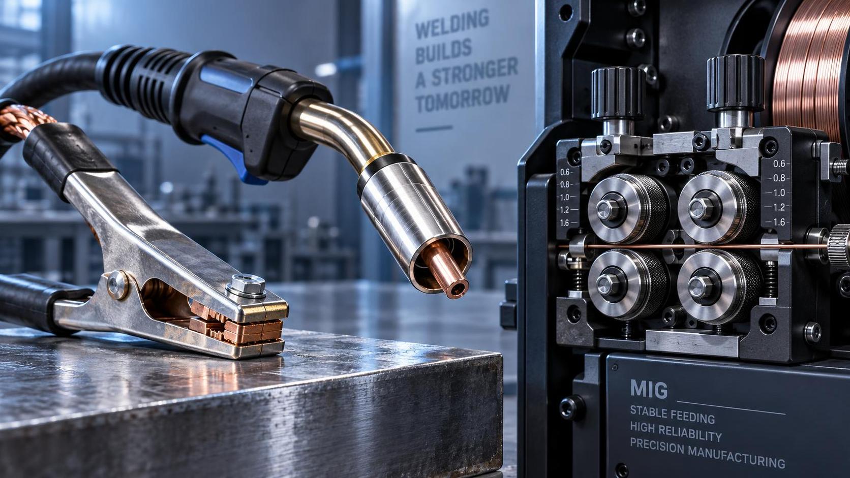
Most arc instability issues aren’t from the power source—they’re from the return path. Inspect the ground clamp jaw for pitting, oxidation, or embedded slag. A shiny, bare-metal contact point is non-negotiable. If the clamp grips painted, rusted, or oily steel, resistance spikes, voltage drops, and the welder compensates by increasing current—often overheating consumables or burning through thin sections. Also trace the entire ground cable: look for kinks, crushed insulation, or exposed copper strands near connectors. A damaged cable doesn’t just reduce conductivity—it creates intermittent arcing at the lug, which degrades the connection over time. Replace any cable showing >10% visible strand breakage. This is especially critical when feeding welds into structural components like H-beams, where consistent thermal input across flange and web determines straightness downstream.
2. Wire Feed System: Drive Roll Groove Alignment & Tension Calibration
MIG wire feed inconsistency rarely comes from motor failure—it comes from mismatched groove depth, worn liners, or incorrect tension. First, visually confirm drive roll grooves match the wire diameter (e.g., 0.035" rolls for 0.035" wire). A groove too deep crushes wire; too shallow slips. Then, manually rotate the drive rolls while feeding wire: if you feel jerking or hear grinding, inspect liner ends for burrs or misalignment at both gun and feeder. Finally, test tension: set to mid-range, then gently pull wire by hand—if it feeds smoothly without slippage *or* deformation, tension is appropriate. Over-tightening stretches wire, causes burnbacks; under-tightening leads to stuttering arcs and poor penetration. In high-volume applications like automated H-beam welding lines, this check prevents micro-variations that accumulate across dozens of passes—directly affecting post-weld straightness and fit-up in downstream processes like YTJ-60B and YTJ-80B H beam straightening machine correction.
3. Gas Flow Verification — Not Just Gauge Reading
A flow meter reading ≠ actual shielding gas delivery at the nozzle. Blockages in the gas diffuser, degraded O-rings in the gun body, or kinked hoses cause laminar-to-turbulent transition—resulting in porosity even with perfect settings. Perform a simple verification: set flow to 35 CFH, ignite arc on scrap, then hold a piece of tissue 2 inches from the nozzle tip. It should deflect steadily—not flutter or stall. If it does, shut down and inspect the gas solenoid valve for debris, clean the diffuser with a soft brass brush (never steel), and replace the gas hose if older than 2 years. Note: CO₂-rich mixes degrade rubber components faster. This step is foundational for weld integrity in load-bearing joints—where porosity isn’t cosmetic; it’s a fatigue initiation site.
4. Torch Consumables: Nozzle, Contact Tip, and Retaining Cap Wear Pattern
Don’t wait for spatter buildup or arc wandering. Examine the contact tip’s inner bore: uniform wear means correct stick-out and travel speed. Oval or off-center wear signals torch angle drift or excessive heat soak—common when welding thick flanges without adequate interpass cooling. Check nozzle spatter rings: if buildup exceeds 1/8", cleaning won’t restore laminar flow—replace it. And inspect the retaining cap threads: cross-threading or galling indicates forceful installation, which misaligns internal gas paths. Replace tips every 8–10 hours of arc-on time in production environments—even if they “look fine.” A worn tip increases resistance, raises voltage, and destabilizes the arc column. In robotic cells, this directly impacts repeatability across hundreds of identical welds.
5. Cooling System Fluid Level & Condition (Liquid-Cooled Systems)
Water-cooled torches and power sources rely on consistent thermal management. Check coolant level *cold*—not after operation—since expansion masks low volume. More importantly, inspect fluid clarity and odor. Milky coolant signals oil contamination (from pump seals); greenish tint with sediment means corrosion inhibitors have depleted. Both drastically reduce heat transfer efficiency. Flush and replace coolant per OEM schedule—but also test pH annually. Coolant below pH 7.5 accelerates copper tube corrosion in torch cables, leading to internal shorts and erratic current delivery. In continuous-duty setups—like those feeding into H-beam production lines—this check prevents thermal shutdowns mid-cycle.
6. Power Source Input Connections & Ventilation Clearance
Loose lugs at the main input terminal are the #1 cause of unexplained voltage fluctuations and breaker tripping under load. Use a torque wrench—not intuition—to verify tightness per manufacturer spec (typically 60–80 in-lb for 6 AWG). Also inspect for discoloration or carbon tracking on terminals: that’s evidence of chronic arcing. Simultaneously, clear all vents—top, side, and rear—of dust, metal shavings, or overspray residue. A clogged vent forces internal fans to work harder, raising component temperature and shortening IGBT lifespan. In shops with multiple high-amperage welders operating simultaneously, inadequate ventilation compounds harmonic distortion on shared circuits—degrading arc performance across the board.
7. Safety Interlocks & Emergency Stop Functionality
This isn’t procedural theater. Test every e-stop button on the welder, robot pendant, and cell perimeter—*with power applied and the system in ready state*. Confirm immediate contactor drop-out and audible relay click. Then verify the wire feeder stops feeding *within 100ms* of activation. Also check door interlocks on robotic cells: open a safety gate while in teach mode—does motion halt instantly? If not, the fault may lie in worn microswitches, loose wiring, or PLC logic delays. In ISO9001- and CE-compliant environments, documented interlock verification is mandatory—not because auditors demand it, but because a delayed stop during torch collision can destroy $20k worth of positioning gear in seconds.
None of these checks require proprietary software or certified calibration tools. They rely on observation, tactile feedback, and understanding how energy flows—from power input, through arc, back to ground, and out as heat and gas. When performed consistently, they transform maintenance from reactive firefighting into predictable, measurable process control. That predictability is what allows fabricators to confidently integrate welding into larger production sequences—whether feeding welded H-beams into precision straightening systems or aligning robotic weld paths with CNC-cut plate edges. It’s not about keeping machines running longer. It’s about ensuring every weld meets the same standard—today, next week, and five years from now.
search
Products Navigation
Send Us A Message