




Butt Welding Equipment and Machines: Understanding Pressure, Temperature, and Flash Control Parameters for Pipe Joint Integrity
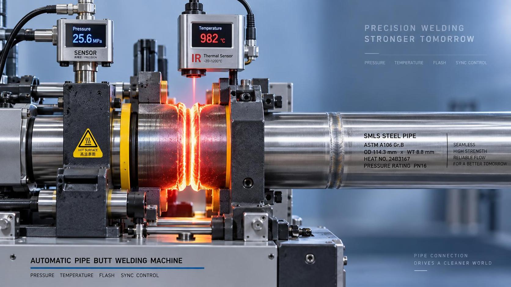
Why “Set-and-Forget” Butt Welding Parameters Are a Myth—And What Actually Ensures Joint Integrity
If you’re evaluating butt welding equipment and machines for pipeline fabrication, pressure, temperature, and flash control aren’t just settings to log in a checklist—they’re interdependent variables whose real-time interaction determines whether a joint passes hydrostatic test or fails under thermal cycling. Technical evaluators often assume that once calibrated, these parameters remain stable across batches. That assumption is where field failures begin.
Pressure Isn’t Just Force—It’s Interface Dynamics
Applied axial pressure during upset must overcome both material flow resistance *and* surface oxide disruption. Too low? Incomplete forge, residual oxides trapped at the interface, microvoids. Too high? Excessive flash extrusion that compromises grain structure continuity at the fusion boundary—especially in duplex stainless or high-alloy steels where hot ductility drops sharply above 1,150°C. Crucially, pressure alone tells you nothing without context: pipe wall thickness, surface roughness (Ra > 3.2 µm increases required force by ~18%), and preheat uniformity all shift the effective pressure window. Modern systems don’t just hold pressure—they monitor displacement rate during upset. A drop below 0.15 mm/s at peak load signals insufficient plastic flow, even if nominal pressure reads within spec.
Temperature Control Is About Gradient Management—Not Just Peak Reading
Thermocouples embedded in heater plates measure surface temperature—not the actual interfacial temperature where metallurgical bonding occurs. In thick-wall (>25 mm) carbon steel pipes, the thermal lag between heater face and pipe ID can exceed 60 seconds. Relying solely on heater-setpoint temperature risks underheating the root zone while overheating the OD. The more reliable indicator is *time-at-temperature*: holding the interface within ±25°C of target for ≥90 seconds ensures sufficient diffusion and recrystallization. This requires closed-loop feedback from infrared pyrometers focused on the pipe end face—not the heater—and adaptive timing logic that adjusts based on ambient humidity and incoming pipe temperature. Systems lacking this capability produce joints with inconsistent grain growth, visible as variable hardness bands in post-weld hardness mapping.
Flash Isn’t Waste—It’s a Diagnostic Signal
Flash geometry—its height, symmetry, and consistency—is the most immediate visual proxy for process stability. Asymmetric flash indicates misalignment (≥0.3° angular deviation), while intermittent flash suggests hydraulic pressure ripple or inconsistent clamping force. But the critical insight isn’t in flash removal—it’s in flash *formation*. If flash volume drops by >15% across three consecutive welds without parameter change, it signals either heater degradation (reduced radiant output), oxide buildup on pipe ends (increasing thermal resistance), or moisture absorption in the heating element insulation. Ignoring this trend leads directly to cold shuts. Effective flash control means monitoring not just final flash height, but its real-time extrusion profile via laser displacement sensors—something only integrated, CE-certified systems with ISO9001-traceable calibration provide.
Where Parameter Interdependence Breaks Down—And How to Mitigate It
The biggest gap in technical evaluation isn’t missing data—it’s missing correlation. Most spec sheets list pressure range, temperature setpoint, and flash removal time as independent specs. In practice, changing one forces recalibration of the others. Example: increasing preheat temperature by 50°C reduces required upset pressure by ~12%, but also increases flash volume by ~22%—which then demands faster flash removal speed to avoid re-oxidation of the hot surface. Without synchronized control logic, operators manually adjust each parameter, introducing drift. This is why leading systems embed adaptive algorithms: they treat pressure, temperature, and flash dynamics as a single state vector, adjusting all three in concert based on real-time displacement and thermal imaging feedback.
Cutting Preparation Matters More Than You Think
No amount of precision in butt welding compensates for poor end preparation. Pipe ends must be cut square (±0.5°), free of burrs, and with surface finish Ra ≤ 1.6 µm—especially for high-integrity applications like sour service or cryogenic lines. Flame-cut ends introduce heat-affected zones up to 2 mm deep with decarburized layers; mechanical sawing leaves micro-tears unless tooling is precisely maintained. This is where upstream processing becomes part of the weld integrity chain. For instance, when preparing stainless steel or nickel alloy pipe ends, a Table type cnc plasma cutting machine delivers consistent edge quality at speeds up to 6,000 mm/min, with kerf widths under 0.75 mm and minimal HAZ—critical for avoiding post-cut machining that introduces contamination or residual stress. Its non-contact arc ignition and pneumatic torch height control maintain dimensional consistency across varying plate thicknesses and surface conditions, reducing the variability that later undermines welding repeatability.
What to Demand in Validation—Beyond the Manual
Don’t accept “calibrated per ISO 9001” as proof of parameter reliability. Ask for: (1) traceable calibration records showing sensor drift over 12 months—not just initial certification; (2) evidence of thermal imaging validation for interface temperature estimation; (3) displacement sensor resolution and sampling rate (≥1 kHz minimum); and (4) audit logs showing parameter adjustments made during production runs—not just static setup files. If the system doesn’t store timestamped, tamper-proof records of pressure, temperature, displacement, and flash extrusion rate for every weld, treat it as a documentation risk—not just a technical one.
Joint integrity isn’t achieved by hitting nominal parameters. It’s confirmed when pressure, temperature, and flash behavior converge within narrow, correlated bands—across shifts, across materials, across environmental conditions. That convergence only emerges from systems designed around process physics—not just compliance checkboxes.
search
Products Navigation
Send Us A Message