




How Automatic Tube Bending Machines Improve Output in Furniture and Auto Parts Manufacturing
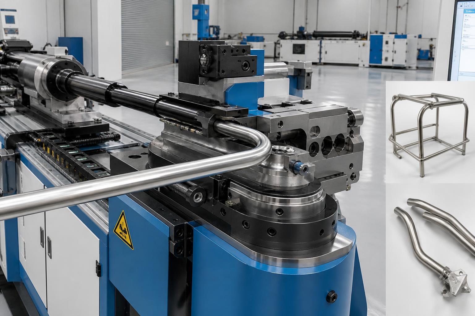
Throughput rises when tube bending stops being a manual fitting exercise and becomes a controlled production step. In furniture frames and auto parts, the delay rarely comes from the bend itself alone. Output is usually constrained by tube loading, program changes, springback correction, part-to-part inconsistency, and downstream rework when bent sections do not match welding fixtures or assembly points. An automatic tube bending machine addresses those losses by combining programmable motion, repeatable clamping, and stable bend sequencing in a way that keeps the line moving with fewer interruptions.
In furniture production, this matters most where the design uses many similar curves across chairs, tables, bed frames, shelving, and tubular support structures. Materials may include mild steel tube for strength, stainless tube for exposed finishes, and aluminum tube where weight reduction matters. Even when wall thickness is modest, inconsistent bending can flatten the outer radius, wrinkle the inner wall, or shift the bend start point enough to create fit-up problems at welding stations. Once that happens, output drops for reasons that are not always visible in machine cycle time reports. Operators spend time adjusting jigs, sorting mismatched parts, or doing local correction work that should not exist in a stable process.
Auto parts manufacturing puts different pressure on the same equipment. Tube geometry may need to match tighter assembly envelopes around brackets, body structures, fluid routing paths, or seat and chassis components. A small deviation in angle, rotation, or cut length can prevent the part from seating correctly in the next fixture. The practical value of an automatic tube bending machine is that it keeps bend angle, feeding length, and rotation under program control, which reduces dependence on operator feel. If the incoming tube condition is reasonably stable, the machine can maintain much closer repeatability over long runs than a manual or semi-manual setup.
Where Output Is Actually Gained
The most obvious improvement is shorter handling time between parts. On manual equipment, the tube often needs to be positioned, aligned, clamped, checked, bent, released, and repositioned by hand for each segment. Multi-bend parts increase the penalty because every repositioning step creates another chance for cumulative error. Automatic systems reduce these pauses through servo-controlled feeding and rotation. The operator loads the material, confirms the program, and monitors the run instead of actively steering every bend. That changes the labor profile of the cell and typically makes scheduling easier when production includes mixed part batches.
Another output gain comes from first-pass conformity. A tube that exits the machine with the correct angle but the wrong spatial orientation is still a bad part. Furniture components with mirrored left and right forms are especially vulnerable to this issue. Auto parts with compound bends are even less forgiving. Automated control of tube rotation between bends helps prevent orientation drift, so fewer parts are rejected at fixture check or pulled aside for manual straightening. In day-to-day production, avoiding these small disruptions often matters more than chasing a theoretical maximum bending speed.
Tool change and recipe recall also affect usable capacity. A shop handling many SKUs can lose substantial time if every model change requires manual setting, trial bends, and repeated correction. Machines with stored programs shorten the recovery time after changeover because feed length, rotation values, bend sequence, and compensation settings can be recalled instead of rebuilt. That is particularly valuable when a line alternates between short furniture batches and longer automotive component runs, where different radii, diameters, and material grades may be scheduled in the same shift.
Process Details That Separate Stable Output from Nominal Output
Tube material condition has a direct effect on bending consistency. Carbon steel, stainless steel, and aluminum do not respond the same way under the same tooling pressure. Even within one material family, differences in temper, weld seam position, wall thickness tolerance, and surface finish can change springback behavior. An automatic tube bending machine improves output only when the program reflects those material realities. If springback compensation is not matched to the actual batch, the machine will produce wrong parts very efficiently. For that reason, stable input material and controlled program validation are part of the productivity equation, not separate issues.
Wall thickness and bend radius need similar attention. Tight-radius bends on thin-wall tube can increase the risk of flattening or wrinkling unless the machine uses suitable tooling, pressure die support, and, where needed, mandrel bending. In furniture work, visible distortion can make a part unusable even when the geometry is technically close. In auto parts, the cosmetic surface may matter less than maintaining cross-section and flow path integrity. Output improves when the selected machine capacity matches real production geometry instead of catalog diameter alone.
A common mistake is to compare machines only by maximum tube diameter. That number does not show whether the machine can hold accuracy on thin-wall stainless, whether it can manage multiple bends close together, or whether it supports the clamping stability needed for high-mix production. Another misjudgment is assuming that higher axis speed always leads to better output. If the machine accelerates quickly but requires frequent correction because tooling setup is unstable, actual line performance may remain poor.
Why Furniture Lines Feel the Difference Quickly
Furniture production often involves repeated families of parts with cosmetic exposure. Tubes may be powder coated, polished, brushed, or plated after forming, so bend marks, scratches, and surface pressure defects become costly. Automatic bending helps because controlled movement tends to reduce random handling damage. It also supports consistent part nesting for welding fixtures, which is critical when many assemblies use shared components such as legs, perimeter frames, arm supports, and stretchers.
Cycle stability is often more useful than raw speed in these environments. A chair frame program with several bends may not be especially demanding in isolation, but output across a full order depends on keeping every frame within the same dimensional window so downstream welding and finishing do not slow down. When the bend start point, angle, and orientation remain consistent, fixtures require fewer adjustments and weld distortion control becomes more predictable. That shortens waiting time between operations even when no single machine appears dramatically faster on paper.
For plants that fabricate both tube and plate features within the same production flow, welding preparation can become another hidden bottleneck. If tubular components are assembled to beveled brackets or thicker structural plates, edge preparation quality affects weld fit-up and handling time. In that context, a plate-processing machine such as Through CNC Milling machine may be used alongside bending equipment for welding preparation on carbon steel, stainless steel, or aluminum plates. A plate-through design with one-pass beveling on both sides can reduce waiting between cutting, edge prep, and fixture assembly, which helps the bending cell deliver parts into a smoother overall workflow rather than into another queue.
Auto Parts Production Adds More Variables
Automotive-related tube parts often require closer control over datum relationships. The bend sequence may need to account for interference between tooling and formed sections, and some parts can only be bent reliably if rotation order is optimized before the first production run. Automatic machines are useful here because they can repeat a validated sequence without relying on manual interpretation each time. If a part has several bends in different planes, that repeatability can prevent the gradual shift that sometimes appears across long runs on less controlled equipment.
Traceability may also matter depending on the component category. Even where full digital integration is not required, stored programs and stable parameter management reduce confusion between revisions. Output suffers when outdated settings remain in use after an engineering change, especially for brackets, seat structures, exhaust-adjacent tubes, or formed reinforcements where a small dimensional shift affects assembly. A machine that supports clear program management can reduce those avoidable stops.
Tube end condition should not be ignored. Burrs, poor cut squareness, or inconsistent starting length can produce alignment issues before bending even begins. In practice, output improves most when cutting, deburring, and bending are treated as linked steps. If cut length varies, the bending program may appear unstable even though the root cause is upstream. This is one reason installation planning should consider material flow around the machine rather than only the machine footprint.
Installation and Layout Influence Productivity
An automatic tube bending machine can underperform in a poorly planned area. Straight material needs enough infeed space, and long formed parts need safe discharge clearance without forcing operators to twist or drag the workpiece. If tubes are manually carried across narrow aisles or stacked without clear orientation control, the gains from automation shrink quickly. The machine should sit where raw tube supply, cut blanks, finished-part racks, and inspection fixtures form a short and predictable path.
Foundation stability and utility quality matter as well. Vibration, uneven leveling, or fluctuating pneumatic supply can affect clamping consistency and axis behavior. On larger or tighter-tolerance work, those factors may show up as intermittent variation that is difficult to diagnose because it does not happen on every part. Proper installation usually includes alignment, trial bending on actual material, verification against the drawing or gauge fixture, and confirmation that the machine maintains repeatability after warm-up.
Transportation and unloading conditions can also have practical consequences. Machines with multiple servo axes, precision tooling stations, and control cabinets should be protected from impact and contamination during shipment. Once received, they should be inspected for transit-related misalignment before production qualification starts. Skipping that step can turn commissioning into a prolonged troubleshooting exercise.
Maintenance Has a Direct Output Effect
In bending operations, maintenance is production control. Worn clamps, contaminated lubrication points, damaged mandrels, and loose alignment references usually show up first as quality drift, not full machine stoppage. That can be more dangerous because output appears normal while reject risk rises. Routine inspection of tooling wear, lubrication condition, hydraulic or servo response, sensor cleanliness, and clamping surfaces helps keep the machine in a repeatable state.
Preventive work should also include checking the relationship between programmed values and actual formed geometry. If a machine gradually requires more compensation to achieve the same result, something in the material, tooling, or axis condition has changed. Treating that drift as normal can hide a developing fault. For furniture plants running exposed-finish stainless, even minor tool wear may leave marks that create downstream polishing work. For auto parts, the same wear may shift bend location enough to affect assembly fit.
Spare tooling strategy matters more than many lines expect. Output can stall when a common radius tool, wiper die, or mandrel component fails and no replacement is ready. Where production involves several tube diameters and materials, it is useful to distinguish between universal service items and geometry-specific tooling so that stocking decisions reflect actual interruption risk rather than broad assumptions.
Choosing by Production Logic Instead of Spec Sheet Noise
The right machine configuration depends on part family, not on abstract feature count. A simple high-volume tube with one or two bends may run well on a more straightforward system if feeding and clamping are stable. A mixed program involving stainless furniture frames, aluminum support parts, and auto components with compound geometry may justify more axis control, better program storage, and stronger compensation capability. Capacity should be judged by tube diameter range, wall thickness, minimum and maximum bend radius, material mix, bend complexity, and changeover frequency together.
It is also useful to ask whether the machine will be paired with welding fixtures, robotic welding, end-forming, or plate-edge preparation. In fabrication environments where bent tubes join machined or beveled plate details, upstream and downstream compatibility can affect total output as much as bending speed. A related process such as Through CNC Milling machine may support welding preparation by forming straight, inclined, U-shaped, V-shaped, or K-shaped bevels in one pass, with common thickness coverage from 6–80mm and some heavy-duty versions reaching 6–400mm, while bevel angle adjustment may extend from 0° to 90°. Details like these matter because a fast bending cell loses value if welded assemblies then wait for edge preparation or manual grinding.
Automatic bending improves output when it is treated as part of a controlled manufacturing route rather than a standalone machine purchase. The strongest gains usually come from fewer interruptions: less manual repositioning, fewer bad bends, shorter changeovers, steadier fixture fit, and lower rework pressure across the line. When material condition, tooling, installation, and maintenance are kept in the same conversation, the machine contributes to real production flow instead of isolated machine utilization.
search
Products Navigation
Send Us A Message