




How does a precision handling robot arm maintain repeatable positioning?
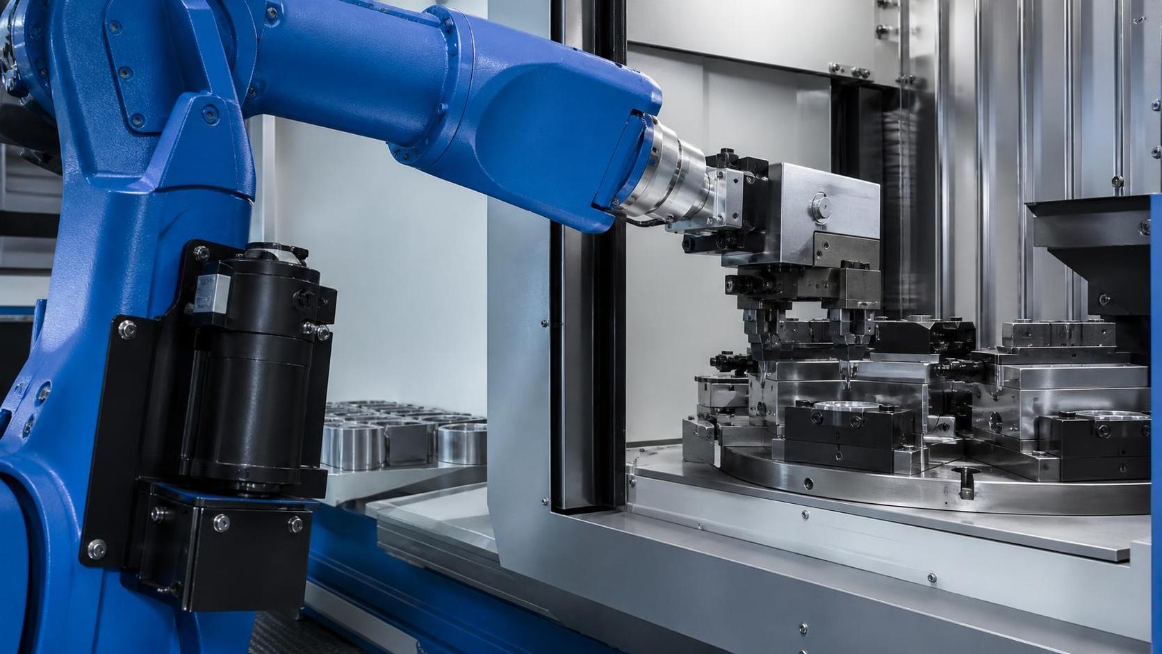
Repeatable positioning is not the same as absolute accuracy. A robot arm may return to the same taught point within a very small tolerance over hundreds of cycles, while that point is still offset from its nominal CAD coordinate. For handling, loading, unloading, fixture transfer, and machine tending, repeatability is often the more immediate concern: the gripper must approach the part, fixture, or station in the same way every time.
A precision handling robot arm achieves this consistency through a connected system rather than one isolated component. Mechanical stiffness limits physical deflection; servo motors and drives control motion; encoders report actual axis position; the controller corrects deviations continuously; calibration connects the robot’s internal coordinates to the real cell. Stable performance depends on all of these elements remaining aligned under the actual payload, speed, temperature, and process conditions.
Repeatability begins with a rigid and predictable mechanical structure
Every robot arm bends slightly under load. Links flex, gearboxes transmit torque through finite clearances, bearings carry radial and axial forces, and the base transfers reaction forces into the floor or machine frame. Precision does not mean that these effects disappear. It means they are reduced, controlled, and made predictable enough for the servo system and calibration model to compensate within the robot’s specified performance range.
The parts most directly connected to repeatable positioning include:
- Arm links and castings: High stiffness reduces elastic deflection when the arm accelerates, stops, or changes orientation with a load.
- Reduction gearboxes: Harmonic, cycloidal, or other precision reducers convert motor motion into joint movement. Low backlash is important because backlash can create a different final joint position depending on the direction of approach.
- Bearings and joint assemblies: Worn or improperly preloaded bearings can introduce play that no software adjustment can reliably remove.
- Base mounting: A robot can meet its factory specification only when installed on a foundation or structure with sufficient stiffness. A flexible pedestal, loose anchor bolts, or an unstable overhead frame changes the robot’s reference condition.
Mechanical rigidity matters most when the robot operates near its maximum reach, carries a high moment load, or makes frequent high-acceleration moves. A payload may be below the rated mass but still create an excessive wrist moment because its center of gravity is far from the flange. This is why payload evaluation must include mass, center of gravity, inertia, gripper weight, cables, brackets, and the workpiece—not just the part weight.
Approach direction is another practical consequence of mechanical compliance. If a placement point is reached from alternating directions, gear tooth loading and joint deflection may not settle identically. Where the process permits, programming a consistent final approach direction and a controlled insertion motion can improve placement consistency without changing hardware.
Servo control closes the gap between commanded and actual motion
A robot controller does not simply send a motor a command and assume that the joint has moved correctly. Each joint uses a closed-loop servo system. The controller commands a position, velocity, and acceleration profile; the servo drive compares the commanded position with feedback from the encoder; the drive adjusts motor torque to reduce the remaining error.
High-resolution encoders are central to this process. Mounted at the motor or, in some designs, at the output side of the joint transmission, they convert shaft rotation into position feedback. Better feedback resolution allows smaller positional corrections, but resolution alone does not determine usable repeatability. Encoder quality, signal integrity, gearbox behavior, tuning of the servo loop, structural vibration, and load modeling all affect the final result.
The controller also uses dynamic models. It estimates the torque needed to move each axis based on robot geometry, gravity, payload, inertia, speed, and acceleration. If the payload data are wrong, the robot may still complete the path, but it will not control the arm under the conditions assumed by the manufacturer. The result can be overshoot, longer settling time, inconsistent path behavior, excessive vibration, or faults during rapid movement.
For this reason, a gripper change should trigger a payload review even if the replacement tool looks similar. A few kilograms added at the wrist, or a modest shift in the center of gravity, can materially change the dynamic load on the final axes. A tool with moving jaws, pneumatic cylinders, or a rotating unit may also have an inertia profile that differs between open and closed states.
Settling time is part of positioning, not wasted time
A robot may arrive at a programmed coordinate before the end effector is stable enough to perform a precise handling action. After deceleration, the arm and tooling can retain residual vibration. The controller may show that the target position has been reached, while the gripper still moves slightly relative to the part or fixture.
This distinction becomes visible in operations such as pin insertion, narrow fixture loading, camera-guided pick-up, and placement near a cutting head or press brake tool. Reducing cycle time by increasing acceleration or eliminating a short settling delay can cause intermittent errors that appear random. In reality, the robot may be repeating the same dynamic behavior, but the process has insufficient tolerance to absorb it.
A sound adjustment sequence is to confirm the tool and payload data, inspect the final approach path, reduce acceleration near the critical point, and then determine whether a dwell or fine-positioning instruction is necessary. Increasing speed should not be the first response to a cycle-time target when the operation is already close to its positional tolerance.
Coordinate frames turn repeatable joints into repeatable work
Robot joints can repeat their angular positions very well, but production depends on the relationship between the robot and the outside world. The controller needs accurate coordinate frames for the robot base, tool center point (TCP), work object, fixture, conveyor, or machine interface.
The TCP is the most important operational reference. It defines the effective point and orientation of the gripper, suction cup, magnetic head, fork, or other end effector. If the TCP is entered incorrectly, the robot may repeat perfectly around an incorrect virtual tool tip. A 2 mm TCP error can become a handling problem at every station, especially when orientation changes during the motion.
Tool calibration should be repeated when any of the following changes:
- the end effector is replaced, repaired, or removed and reinstalled;
- a gripper finger, suction cup, locator pin, or extension bracket is changed;
- the tool is struck, dropped, or subjected to a collision stop;
- the wrist adapter or quick-change interface is loosened or repositioned;
- the process reveals a persistent offset that is not explained by the part or fixture.
Work-object calibration is equally important. A fixture is not necessarily in the same location after maintenance, changeover, thermal movement, or accidental contact. Teaching points by jogging the robot to a feature can conceal a fixture shift, because the robot program may be corrected locally while the underlying reference frame remains wrong. Re-establishing the work frame gives a more traceable correction and protects the logic of the program.
For coordinated systems, the reference chain is longer. A robot tending a CNC machine, transfer station, or laser-processing cell must be aligned not only to a fixture but also to the machine datum, material position, and process coordinate system. For example, the stated positioning accuracy of a Pipe cnc fiber laser cutting machine is meaningful only when chuck clamping, tube straightness, machine axes, program zero, and robot loading location are controlled as one system. A repeatable robot cannot compensate for a tube that shifts in the chuck or a datum that has been reset incorrectly.
Absolute accuracy and repeatability should not be confused
Industrial robot specifications frequently distinguish between pose accuracy and pose repeatability. ISO 9283, Manipulating industrial robots—Performance criteria and related test methods, provides a recognized framework for evaluating such performance characteristics under defined test conditions. The test arrangement, payload, speed, environmental conditions, pose distribution, and measurement method matter. A catalog value is therefore not a blanket guarantee for every cell layout and every point in the workspace.
Repeatability describes how closely the robot returns to a previously reached pose. Accuracy describes how closely it reaches a commanded or reference pose. A handling task that always picks from a fixed nest and places into a tolerant fixture may function well with strong repeatability even if absolute accuracy is less impressive. Offline programming, interchangeable fixtures, multi-station cells, and processes that rely on CAD coordinates place greater demands on absolute accuracy and calibration.
Vision systems can correct variation in part position, but they do not replace a stable mechanical and coordinate foundation. Camera calibration, lens mounting, lighting, trigger timing, and the transform between camera and robot coordinates all introduce their own uncertainty. Vision is most effective when it compensates for identifiable part variation, not when it is used to mask robot backlash, damaged tooling, or drifting fixtures.
What gradually degrades repeatable positioning
Loss of repeatability is often gradual. Operators may first notice that a placement point needs occasional touch-up, a gripper begins to contact one side of a nest, or a machine door clearance becomes inconsistent. Treating these symptoms as isolated programming issues can delay the real diagnosis.
Common sources include loose mounting hardware, collision damage, gearbox wear, contaminated or damaged locator surfaces, worn gripper fingers, unstable air pressure, cable drag, and changes to the end effector that were not reflected in the controller data. In applications with heavy welding spatter, abrasive dust, coolant mist, or metal chips, contamination can affect both the robot environment and the repeatability of the fixture itself.
Temperature also deserves attention. Motors, gearboxes, bearings, and surrounding structures change dimension as they warm. In a demanding cycle, a robot may behave differently immediately after start-up than after sustained operation. This does not automatically indicate a fault. It does mean that precision-sensitive teaching, validation, and measurement should be performed under operating conditions that represent normal production.
External forces are a further source of error. A robot that contacts a part during insertion, pulls against a stiff cable bundle, or presses into a locating feature can deflect. Force-control functions may be appropriate for designed contact tasks, but they need correctly defined limits and a fixture capable of absorbing the intended load. A conventional position-controlled placement should not rely on repeated contact to find its final location unless the process was designed for compliant insertion.
Daily practices that preserve accuracy
Repeatable positioning is protected through disciplined operation more than frequent retouching. Before a production run, verify that the correct robot program, tool frame, work frame, payload setting, and end-effector configuration are active. A program can be technically valid yet unsuitable if it calls a TCP associated with another gripper or a fixture frame from a previous setup.
During operation, watch for changes rather than only faults. Unusual vibration during deceleration, a new clicking sound at a joint, longer time to settle, cable snagging, altered gripper closing behavior, or the need to alter taught points are useful warning signals. A collision should be documented and followed by inspection of the tool, flange, mounting bolts, fixture, and calibration—not merely a restart.
Clean locating surfaces and gripper contact faces at the frequency required by the material and process. A thin layer of chips, spatter, oil, or protective film can displace a part enough to look like a robot error. Verify pneumatic gripping force or vacuum level where these are part of part location. The robot may place exactly where commanded while the workpiece sits differently in the end effector.
When a point must be adjusted, distinguish between a global reference error and a local process error. If many points have shifted by a similar amount, inspect the TCP, work frame, fixture position, and robot base condition. If only one pick or place point fails, inspect the local nest, part presentation, gripper geometry, and approach path. Changing every affected taught point is rarely the best first action; it can create hidden inconsistencies and complicate later recovery.
Reliable repeatability is a system condition
A precision handling robot arm maintains repeatable positioning because its mechanical structure, transmission system, feedback devices, control loops, and calibration data work together within defined load and motion limits. The robot’s specification establishes a capability, but the installed cell determines whether that capability is preserved.
The most useful operational rule is simple: when positioning becomes inconsistent, do not assume the robot has “lost accuracy.” Check the reference chain from part and fixture through the end effector, TCP, payload model, robot mounting, and servo behavior. That approach separates a true robot issue from the much more common causes of placement variation around it, and it prevents small production deviations from becoming permanent programming workarounds.
search
Products Navigation
Send Us A Message