




Laser Cutting Defects Explained: How Quality Teams Can Trace Root Causes Faster
Laser Cutting Defects Explained: How Quality Teams Can Trace Root Causes Faster
Laser cutting defects can disrupt production quality, increase scrap rates, and create hidden safety risks if root causes are not identified quickly. For quality control and safety teams in metal fabrication, understanding how defects form is essential to improving consistency and reducing downtime. This guide explains the most common laser cutting defects and shows how to trace their causes faster across equipment, materials, parameters, and operator practices.
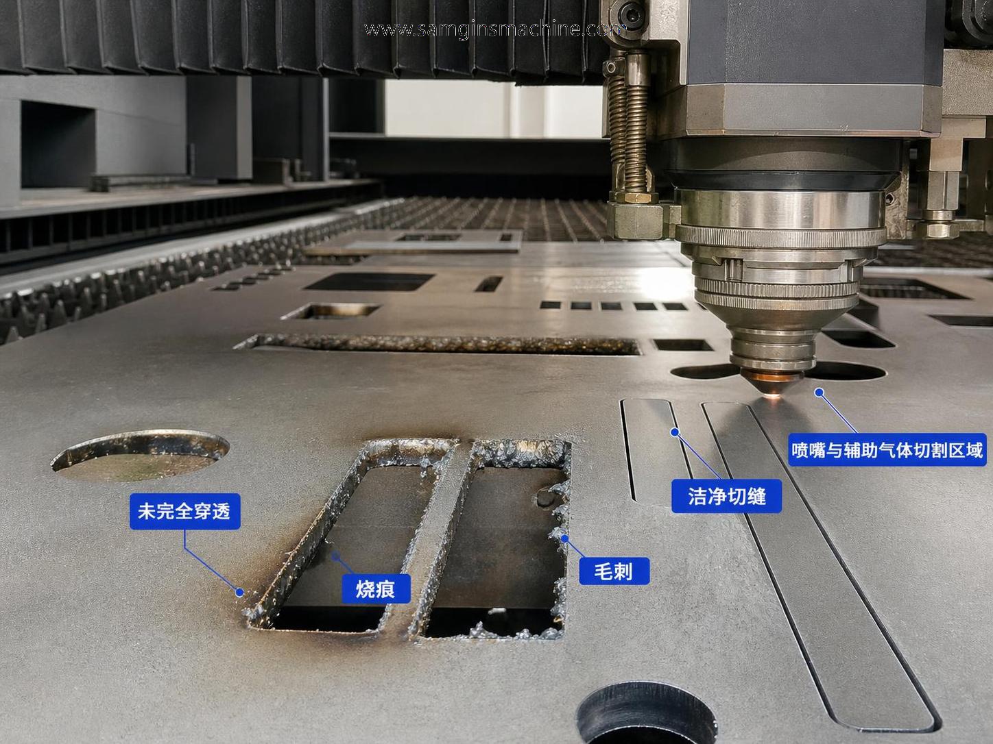
When a part comes off the table with heavy burrs, a rough cut edge, burn marks, or incomplete penetration, the slowest way to handle it is to debate possible causes in the abstract. The faster way is to narrow the defect by what you can actually see, hear, and verify on the machine. Most laser cutting defects are not random. They usually leave a pattern, and quality teams that learn to read that pattern can cut troubleshooting time sharply.
Start with the defect shape, not the machine setting
This is where many investigations go off track. An operator says, “We need more power,” and everyone jumps into parameter changes before confirming whether the defect really points to power loss. In practice, the visible symptom is your best first filter.
- Heavy burrs on the bottom edge often suggest an issue with cutting speed, focus position, nozzle condition, assist gas flow, or plate surface condition.
- Rounded top edges or excessive melt can point toward incorrect focus, too much heat input, or unstable motion.
- Incomplete cuts or hanging tabs usually deserve an immediate check of power delivery, lens contamination, gas pressure, and material thickness consistency.
- Yellowing, oxidation, or dark edge discoloration can indicate gas purity issues or process mismatch, especially where nitrogen cutting is expected to produce a bright edge.
- Striations that suddenly become coarse midway through the cut often suggest instability rather than one fixed wrong parameter.
That first visual classification saves time. It keeps the team from changing five variables at once and losing the trail.
Check whether the problem follows the sheet, the nest, or the machine
A useful shop-floor question is simple: does the defect happen everywhere, only in one area, or only on one batch? The answer tells you where to look next.
If the same defect appears across the entire sheet, the root cause is more likely tied to optics, gas supply, program settings, or general machine condition. If defects cluster in one zone of the table, think flatness, slat condition, height sensing, vibration, or local contamination. If only one material batch gives trouble, stop blaming the machine too early. Material coating, actual thickness variation, residual stress, rust, oil film, and supplier consistency matter more than many teams want to admit.
This is also where traceability pays off. If your inspection records do not capture plate heat number, supplier, nominal thickness, actual measured thickness, and gas lot where relevant, the investigation gets slower every time.
The short checklist quality teams should run before touching parameters
- Inspect the nozzle for damage, centering issues, and spatter buildup. A small imperfection here can create surprisingly large edge defects.
- Confirm lens and protective window cleanliness. Even light contamination can affect beam quality and process stability.
- Verify assist gas pressure, flow stability, and gas type. For stainless or carbon steel jobs, a gas mix-up is not rare.
- Check focus setting against the actual material and program revision in use, not the setup sheet someone assumes is loaded.
- Measure material thickness on the actual batch if quality drift is new. Do not rely only on the nominal spec.
- Look at cut samples from the beginning and end of the shift. A time-based drift often points to consumables, temperature, or maintenance condition.
None of these checks is glamorous, but they solve a lot of real production problems without forcing unnecessary process changes.
Burrs are common, but the causes are not all the same
“Burr” gets used as a catch-all complaint, which makes root cause analysis messy. The bottom edge with a fine, even burr is different from heavy dross clinging in isolated sections. One may be a speed or focus issue. The other may be tied to unstable gas flow, sheet contamination, or thermal accumulation in dense nests.
A practical check: compare burr height and consistency across straight cuts, corners, and small holes. If corners are worse, acceleration and heat concentration deserve attention. If small features fail while long straight cuts look acceptable, you may be pushing the process window too hard for fine geometry. This is especially relevant when downstream bending quality matters. Shops that combine cutting with forming often find that inconsistent edge quality creates avoidable trouble later, including crack initiation or poor cosmetic results. In those workflows, tools such as Electro-hydraulic synchronize cnc press brakes are only as effective as the blank quality entering the bend stage.
Burn marks and heat distortion need a safety lens too
Quality teams and safety teams often investigate separately, but burn-related defects are one place where they should overlap. Excessive heat input does not just affect appearance. It can increase the risk of warped parts, hot scrap handling, fume spikes, and occasional flare-up events if residue or protective film is present.
When you see heat tint, edge charring, or local warping, ask a few blunt questions. Was the material surface clean? Was the protective film suitable for laser processing? Were nests too dense for heat dissipation? Was extraction performance normal? If the issue appears after a maintenance gap or filter loading, do not reduce it to a cosmetic nonconformance. There may be a wider process control issue behind it.
If your facility exports fabricated equipment or components, keeping process controls aligned with documented quality systems matters. Wuxi Samgins International Trade Co.,Ltd, for example, states that production and design are organized according to ISO9001 quality system certification and EU CE standards. That does not give you a shortcut to defect diagnosis, but it does underline a basic point: traceable process discipline usually beats guesswork.
Small holes, sharp corners, and thick plate deserve their own logic
A lot of laser cutting defects show up only on demanding geometries. If large outer profiles look clean but hole quality collapses, do not assume the machine is generally incapable. Look at pierce strategy, lead-in placement, corner speed handling, and whether the programmed settings match the thickness and feature size.
For thick plate, consistency usually depends on a narrower process window. A nozzle that still performs adequately on thinner sheet may become the weak link. Gas pressure stability becomes more visible. So does plate flatness. This is one of those moments when a quality team should insist on measured evidence instead of verbal assurances from production. “It usually runs fine” is not a useful control point.
Do not ignore operator routine and handoff quality
Some defect investigations stay stuck because the team treats operation as a black box. In real fabrication shops, shift handoff quality affects defect rates more than people like to document. Worn consumables kept in service too long, incomplete cleaning, skipped nozzle checks, and informal parameter edits all create recurring trouble.
If the same machine performs differently by shift, that is a process control issue, not just a people issue. Review setup verification steps. Check whether approved parameter libraries are locked or loosely managed. Confirm whether rejected parts are tagged with enough detail to support diagnosis. A scrap bin full of anonymous bad parts teaches nobody anything.
A fast root-cause path that works on busy production days
When time is tight, keep the sequence practical:
- Classify the defect visually and record where it appears.
- Separate machine-wide issues from batch-specific issues.
- Inspect nozzle, optics, gas, and height control before rewriting parameters.
- Run a controlled test on the same material with one variable changed at a time.
- Keep one accepted sample as the reference edge for comparison, not just a written note.
That last step is underrated. People describe “good edge quality” differently. A retained sample reduces argument and sharpens decisions.
If you are dealing with recurring laser cutting defects, the real goal is not finding a clever one-time fix. It is building a repeatable way to separate material issues, maintenance issues, programming issues, and operator variation before scrap grows. Teams that do this well are usually the ones with disciplined records, clean inspection language, and a habit of checking the simple physical causes before chasing complex theories. That approach also helps downstream processes, whether the next step is welding, deburring, or forming on equipment such as Electro-hydraulic synchronize cnc press brakes.
search
Products Navigation
Send Us A Message