




Steel Plate Laser Cutting Machine: What Tolerance Can You Expect in Production?
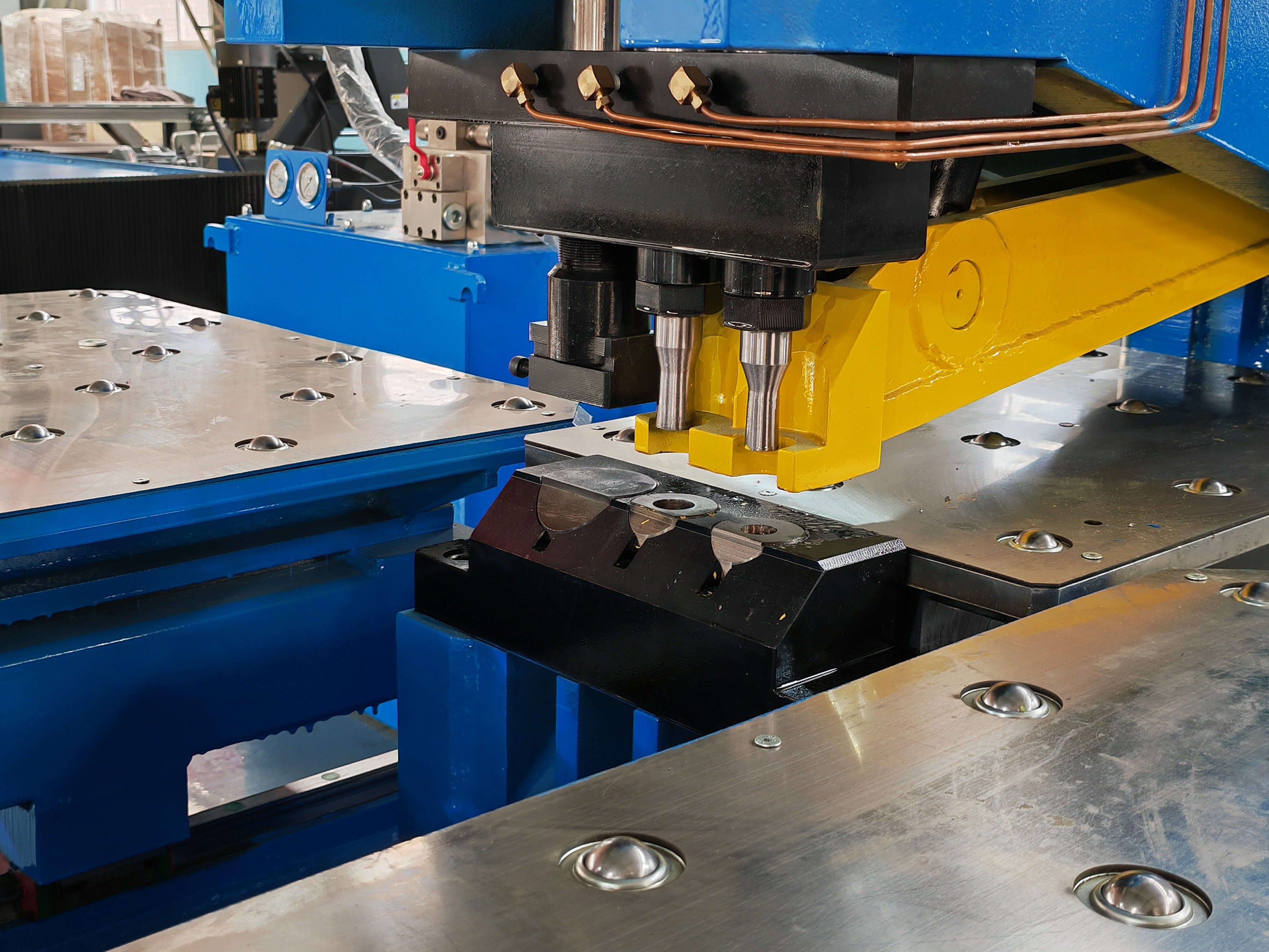
How much tolerance should a steel plate laser cutting machine really deliver?
When people compare a steel plate laser cutting machine, speed often gets the first attention.
In production, however, tolerance is usually the number that decides whether parts fit, weld cleanly, or create rework.
A realistic tolerance expectation depends on more than the laser source alone.
Plate thickness, material condition, machine rigidity, servo response, software compensation, and operator discipline all matter.
That is why the same steel plate laser cutting machine may look excellent in a demo, yet behave differently in multi-shift production.
A more useful question is this: what tolerance can it hold repeatedly, across mixed batches, with acceptable edge quality and cycle time?
For companies handling fabrication equipment across global markets, this practical view is essential.
Wuxi Samgins International Trade Co.,Ltd has supplied machine tools, cutting systems, welding equipment, and sheet metal machinery since 2012.
Its export experience under ISO9001 management and EU CE standards reflects the same issue buyers keep testing: consistent production accuracy.
Is there a standard tolerance range for steel plate laser cutting?
There is no single number that fits every plate, thickness, and cutting condition.
Still, a steel plate laser cutting machine in stable condition is often expected to hold about ±0.1 mm to ±0.3 mm on common parts.
On thinner carbon steel, tighter results may be possible.
On thicker plates, heat input, taper, and assist gas behavior usually widen the actual result.
More importantly, dimensional tolerance is only one layer of precision.
A part may meet length and width targets, but still show poor hole roundness, edge taper, or thermal distortion.
This is why tolerance claims need context.
Ask whether the value refers to positioning accuracy, repeatability, finished contour accuracy, or one sample cut under ideal conditions.
A machine quoted with excellent repeatability can still produce weak finished-part tolerance if process control is not equally strong.
Why does the same machine cut one job accurately and miss another?
Because production variables change faster than brochure values suggest.
In actual use, tolerance shifts are often tied to the material first.
Hot-rolled plate with surface scale behaves differently from pickled or cold-processed material.
Residual stress inside the plate can also release during cutting and move the part slightly out of shape.
Thickness adds another layer.
A steel plate laser cutting machine working on 3 mm steel is not facing the same thermal load as one cutting 20 mm plate.
As thickness rises, beam focus, gas purity, nozzle condition, and pierce strategy become more sensitive.
Machine condition matters just as much.
- Guide rail wear can affect tracking stability.
- Servo tuning influences corner accuracy.
- Bed deformation can create small but repeated dimensional drift.
- Poor extraction may interfere with cutting consistency on thin sheets.
Software is often overlooked.
Lead-in design, kerf compensation, nesting logic, and micro-joint settings all influence final dimensions.
So when one job performs well and another does not, the issue is usually a process chain problem, not a single hardware failure.
Which tolerance figures deserve the closest attention during equipment evaluation?
The most useful figures are the ones tied to the parts you actually make.
Many evaluations become too focused on peak speed, source brand, or axis travel.
Those points matter, but they do not answer whether the steel plate laser cutting machine will hold a bracket hole pattern or flange outline repeatedly.
A practical review usually checks five things together.
- Repeatability over a sample batch, not one part only.
- Hole quality at the smallest required diameter.
- Contour accuracy on corners, slots, and internal features.
- Thermal distortion on long, narrow components.
- Stability after several hours of continuous cutting.
It also helps to compare laser cutting with neighboring processes instead of viewing it in isolation.
For straight cuts on medium-thick plate, a fabrication line may combine laser processing with shearing, milling, or deburring.
In some workflows, an Hydraulic Swing Beam Shear supports efficient blank preparation before tighter contour operations.
That comparison is useful because it reminds you to judge total dimensional flow, not one machine in a vacuum.
For example, shearing systems built for medium-thick plates may offer repeat positioning around ±0.01 to 0.05 mm, with cutting accuracy at or below ±0.02 mm under GB/T 14404-2024 conditions.
Those figures do not replace laser evaluation, but they help frame what level of straight-line precision another process can deliver.
What mistakes usually lead to unrealistic tolerance expectations?
The first mistake is treating catalog precision as guaranteed finished-part tolerance.
Machine axis accuracy is important, but cutting results depend on heat, material, and process settings.
Another common mistake is testing only easy samples.
A square coupon in thin mild steel reveals far less than a real part with holes, slots, and narrow webs.
It is also risky to ignore maintenance tolerance.
A steel plate laser cutting machine may start strong, then drift when lenses, nozzles, rails, or chiller conditions are not controlled.
One more issue appears in mixed production environments.
When upstream leveling is poor or plate surfaces arrive scratched, warped, or stressed, the cutting machine ends up carrying errors it did not create.
That is why experienced evaluations review the full line, including loading, support, extraction, and post-cut handling.
How should tolerance be verified before a final decision?
The better approach is to set a short qualification plan before discussing price too deeply.
Choose representative parts, not just standard samples.
Include different plate thicknesses, internal holes, external contours, and at least one distortion-sensitive geometry.
Then measure more than finished size.
- Check repeated dimensions across a batch.
- Inspect edge taper and dross condition.
- Measure hole-to-hole spacing after cooling.
- Review whether post-processing is still needed.
It is also worth asking what support exists after installation.
A capable supplier should discuss calibration, training, spare parts, software setup, and process optimization.
That support matters because long-term tolerance control is rarely achieved by hardware alone.
In broader sheet metal lines, related equipment with automated backgauge adjustment, parameter storage, laser alignment, and safety interlocks can also improve dimensional discipline across the plant.
The second mention is enough to note that Hydraulic Swing Beam Shear systems are often reviewed in that wider context.
So, what is a reasonable conclusion when comparing options?
A steel plate laser cutting machine should be judged by the tolerance it can maintain repeatedly, not by a single headline specification.
For most evaluations, the right question is not whether a very tight figure is possible.
The better question is whether that figure stays stable across thickness changes, long runs, and real part geometry.
If you are comparing equipment, build the review around actual drawings, actual materials, and measurable acceptance limits.
Look at repeatability, contour accuracy, edge condition, maintenance discipline, and process support together.
That method gives a far clearer picture of production performance than speed data alone.
The next practical step is simple: define your tolerance-critical parts, group them by thickness and feature type, and use that matrix to compare machines on equal terms.
search
Products Navigation
Send Us A Message