




What Shearing Machine Setup Fits a Steel Structure Processing Line?
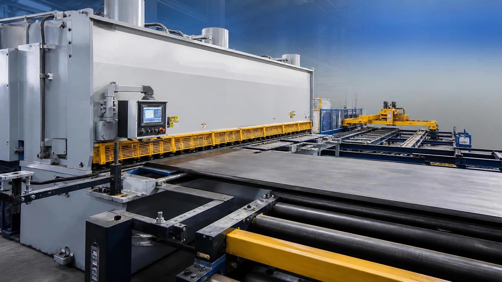
For a steel structure processing line, the right shearing machine setup usually starts with the plate range that actually enters the line: material grade, thickness, width, incoming flatness, and whether parts go next to drilling, assembly, beveling, or welding. A machine that looks adequate on maximum thickness alone can still become the wrong choice if the line handles long strips for stiffeners, frequent width changes, or heavy plate that must keep a stable edge for fit-up. In practice, the question is not only whether the machine can cut the plate, but whether it can do so repeatedly without slowing the rest of the line or introducing edge conditions that create extra work downstream.
In steel structure fabrication, the most common shearing demand sits around carbon steel plate used for base plates, gusset plates, web connection pieces, cover plates, rib plates, and general reinforcement parts. If the line also handles stainless steel or high-strength low-alloy material, setup margins should be treated more cautiously because shear force, blade wear behavior, and cut-edge quality may differ from mild steel. The usable range should be defined by the thickest and widest plate cut in regular production, not by rare emergency jobs. A line built around mostly medium plate often benefits from a guillotine shear with enough frame rigidity to hold blade clearance consistently across the cutting width. If thinner sheet appears frequently, cycle speed and back gauge response may affect productivity more than raw tonnage.
Capacity must match the plate mix, not the nameplate alone
A steel structure line tends to combine several plate families rather than one uniform stock size. One batch may be narrow stiffener strips from 6 mm plate, followed by wider connection plates in 16 mm material, then occasional heavier base plate blanks. Because of that variation, a shearing machine configuration fits a steel structure processing line only when the rated thickness, blade length, and drive system are aligned with the real production mix. Oversizing too far can raise power demand, floor loading, and machine cost without improving cut quality on the materials processed every day. Undersizing creates a more expensive problem: operators start changing routing, splitting cuts, or sending work to thermal cutting stations that should be reserved for shaped parts.
Blade length is often underestimated. A machine chosen by thickness only may force repeated repositioning when longer plate widths arrive. Repositioning does not just add handling time. It can also introduce mismatch at the overlap if the plate is not held firmly, especially on painted, scaled, or slightly warped stock. For straight rectangular blanks, one full-width stroke is usually preferable to staged cutting.
The drive type also matters. Hydraulic shears are common in steel fabrication because they tolerate heavy duty work and provide stable cutting force. Mechanical shears may suit certain high-speed, lighter-gauge applications, but in structural plate processing the hydraulic arrangement is generally easier to match with variable workloads and heavier sections. When the line expects intermittent heavy cuts rather than nonstop thin-gauge production, hydraulic performance often makes more sense.
Choose the shear style according to part geometry and flow
Two configurations are usually considered first: swing beam shears and guillotine shears. Both can cut structural plate, but they behave differently under load and across thickness ranges.
Swing beam machines are often selected for straightforward work with consistent plate ranges. Their structure can be simpler, and they may perform well for common blanking tasks where edge condition requirements are moderate. Guillotine shears are frequently preferred when wider material variation, tighter cut quality expectations, or heavier plate are involved. Because the upper blade moves in a more vertical path, clearance control and cut consistency can be easier to manage across different jobs, provided the machine is properly set and maintained.
If the processing line feeds parts directly into fit-up and welding stations with limited allowance for secondary edge correction, a guillotine design may be the safer choice. If the shear mainly prepares rough blanks for later machining, drilling, or thermal contour cutting, the selection can be more flexible. The correct answer depends on whether the sheared edge is a final working edge or simply a stock-preparation edge.
Blade clearance adjustment is one of the most important details
Many problems attributed to machine quality actually begin with blade clearance that does not match the plate thickness and material condition. Too little clearance can accelerate blade wear, increase burr, and overload the frame. Too much clearance may produce excessive rollover, edge tearing, or a cut face that complicates later assembly. On a steel structure processing line that shifts between different plate thicknesses, manual clearance adjustment can be workable if changes are infrequent and operators are disciplined. Where thickness changes happen often, powered or automatic blade clearance adjustment can remove a recurring source of inconsistency.
This is especially relevant when the line mixes plain carbon steel with higher-strength plate. Even if nominal thickness stays the same, the force required and the way the edge fractures may differ. A setup that cuts one material acceptably may leave another with a rougher fracture zone or a burr that interferes with close-contact joint preparation. If edge quality affects welding gap control, clearance repeatability becomes part of line stability, not just a maintenance preference.
Back gauge configuration determines whether the machine is efficient or frustrating
In structural fabrication, many parts are simple rectangles, strips, and tabs, so the back gauge does more work than people sometimes expect. A short-travel or low-rigidity gauge can be acceptable for small pieces yet become a bottleneck on long blanks. Gauge accuracy should be considered together with sheet support, stop fingers, and operator access. When long narrow strips are common, support in front of the machine matters because material sag can shift the effective dimension even if the gauge itself is accurate.
A useful setup may include:
- CNC back gauge control for repeated dimensions and job recall, especially where batch changes are frequent.
- Long enough travel to cover the dominant part lengths without improvised repositioning.
- Stable stop design that does not deflect easily under heavier plate contact.
- Front support arms or transfer support so wide plates can be presented square to the blades.
If the line processes many short pieces from longer stock, programmable sequencing can save time and reduce measuring errors. If most parts are one-off or highly variable, a simpler gauge may still be sufficient, but it should not compromise squareness or require excessive manual marking.
Material handling around the machine often decides real throughput
When people ask what shearing machine configuration fits a steel structure processing line, they often focus on the machine body and ignore loading and unloading. In reality, heavy plate movement around the shear can absorb more time than the cut itself. A well-matched setup may need roller tables, side supports, front feeding arms, or a discharge table sized for the typical plate format. Without support, operators may drag plates into position, which affects squareness, surface condition, and safety.
For lines connected to storage racks, shot blasting, marking, or drilling, the orientation of material flow should be reviewed before machine selection. A shear placed in the wrong direction can create repeated turning of long plate strips or force forklift traffic through the same area used for finished parts. If the plant handles long members and plate components together, aisle width and crane coverage become part of the shearing setup decision. Even a technically suitable shear can perform poorly if the surrounding handling pattern is awkward.
On heavier lines, hydraulic sheet support or pneumatic support can help prevent the plate from dropping as the cut completes. That is not only a convenience feature. It can reduce edge marking, keep narrow offcuts from twisting, and improve handling of larger blanks that must stay flat for downstream welding assemblies.
Edge quality should be judged by downstream operations
A sheared edge in steel structure work does not always need the finish expected in precision sheet metal. Still, it must be suitable for what comes next. If the part moves directly into welding, the edge should be free from severe burr, major distortion, and cracking at the fracture zone. If the blank will later be machined, some edge deformation may be acceptable. If the part is used in visible architectural steel, cosmetic consistency may matter more than in general industrial frames.
The cut edge is influenced by blade condition, hold-down force, clearance, material surface hardness, and plate flatness. Mill scale can change how the plate seats under the hold-downs. Slight bowing or residual stress in the plate can cause movement during cutting, especially on narrower pieces. For that reason, edge quality should be evaluated on the actual material family expected in production rather than on a generic test plate. A machine trial based only on thin, clean stock may not show the issues that appear on wider structural plate with scale, camber, or residual tension.
Automation level should reflect batch variability
A fully manual machine can still serve part of the steel structure sector if jobs are simple and thickness changes are limited. However, once the line mixes many dimensions and repeat orders, CNC control starts to matter. Stored programs, automatic gauge positioning, stroke length control, and blade clearance adjustment can shorten setup changes and reduce the dimensional drift that appears when settings are changed by feel.
That does not mean the highest automation package is automatically the best match. If the line mainly shears standard strips and common plate blanks, excessive automation may add maintenance burden without changing throughput much. The better question is which settings are changed frequently enough to deserve automation. Usually the strongest candidates are back gauge position, stroke optimization, cutting angle or rake adjustment where available, and blade clearance. A line with limited product variation may get most of the practical value from only one or two of those features.
Pay attention to cutting angle, hold-downs, and frame rigidity
Three mechanical details have an outsized effect on performance. The first is cutting angle. A larger rake angle can reduce peak cutting force, which may help on thicker plate, but it can also increase twist or distortion on narrow strips. If strip straightness matters for later welding or assembly, that tradeoff should be examined carefully.
The second is hold-down performance. Plates that lift or shift during the stroke can lose dimension and develop uneven cut quality from one end to the other. On scaled structural steel, adequate hold-down force is especially useful because the surface is not always perfectly uniform. Worn or poorly distributed hold-downs can leave marks in some conditions, so their contact arrangement matters as much as raw pressure.
The third is frame rigidity. Heavy structural plate cutting loads the machine unevenly, particularly during partial-width cuts or when narrower pieces are taken from one side repeatedly. A rigid frame helps maintain blade alignment and consistent clearance. This becomes more important where the line expects regular work near the upper end of the machine's practical range.
Some common selection mistakes are easy to avoid
One frequent mistake is specifying the machine for maximum thickness and overlooking the dominant width and length of daily jobs. Another is assuming that all straight-cut blanks should go through the shear, even when some heavier or harder materials might be better routed to thermal cutting to avoid excessive wear or edge condition issues. A third mistake appears during layout planning: leaving too little space in front of the machine for plate presentation, then discovering that accurate feeding of wide material is difficult.
There is also a tendency to undervalue blade maintenance. In a structural line, blades may stay in service while edge quality has already started to drift beyond what assembly can comfortably absorb. Rotating or replacing blades at the right interval can prevent a chain of minor corrections later, such as grinding burrs, forcing fit-up, or adjusting weld gaps.
Transport and installation details deserve attention as well. A heavy shear may require foundation preparation, level checking, hydraulic oil commissioning, and verification of power supply compatibility before it can cut consistently. If the machine is placed on an insufficient base or installed without proper leveling, the resulting issues may show up as squareness variation or uneven blade wear rather than an obvious startup failure.
Maintenance expectations should be part of the original setup decision
A steel structure processing line rarely operates in laboratory conditions. Dust, scale, offcuts, and intermittent shock loads are common. The shearing machine configuration should therefore be judged partly by service access. Blade change accessibility, lubrication points, hydraulic component layout, and the ease of cleaning gauge areas all influence long-term usability. A technically advanced machine can become difficult to keep stable if routine service is awkward and adjustment points are hard to reach.
Hydraulic system temperature behavior is another practical issue. In warmer workshops or during long production periods, oil condition and cooling arrangement may affect repeatability. Electrical cabinets should also be considered in relation to shop dust and ambient conditions. These points are mundane, but in continuous fabrication they often separate a stable installation from a troublesome one.
If the line processes mostly standard structural plate with recurring dimensions, a practical configuration is often a hydraulic guillotine shear with CNC back gauge, sufficient blade length for full-width cuts on the common plate format, adjustable blade clearance, reliable hold-downs, and material support sized for the actual plate handling pattern. If workloads are lighter and more repetitive, a simpler arrangement may be enough. The correct fit comes from matching cutting behavior, changeover frequency, and handling conditions to the way the line really runs on the shop floor.
search
Products Navigation
Send Us A Message