




When Does a Custom Handling Robot Suit Irregular Loads and Tight Workcells?
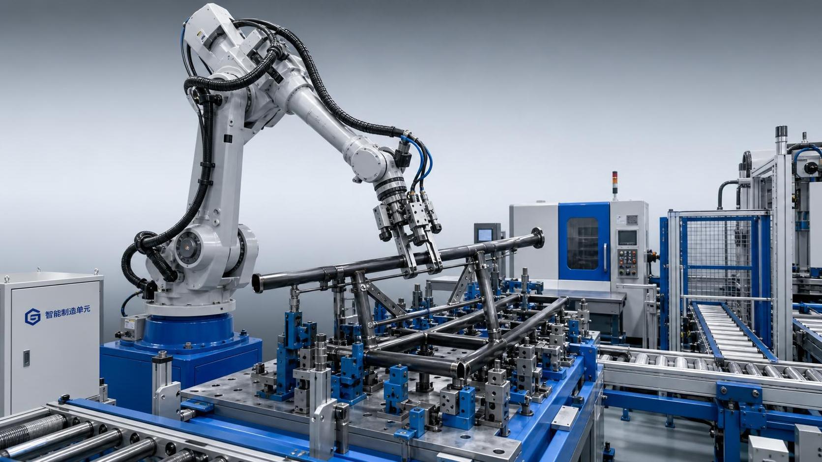
A custom handling robot is justified when the load and the available space defeat the assumptions built into standard palletizing, pick-and-place, or machine-tending cells. The decisive issue is not simply whether a robot can lift the part. It is whether the complete system can repeatedly locate, grip, move, orient, and release a changing or awkward workpiece without creating new safety, throughput, maintenance, or changeover problems.
Irregular loads include more than visibly complex parts. A flat plate with unstable edge conditions, a welded frame with an off-center center of gravity, a long tube that flexes during acceleration, a mixed batch of castings, or a stack with inconsistent separation can all behave unpredictably in a conventional automated cell. In a tight workcell, the handling challenge becomes harder because the robot, end effector, fixtures, safety devices, infeed and outfeed paths must share limited volume without restricting access for operators or maintenance.
The practical question is therefore not “Can automation be added?” but “Can a tailored robotic system remove the unstable part of the process while remaining controllable under real production variation?”
Where standard handling cells begin to fail
A catalog robot cell is usually designed around stable assumptions: a known part envelope, consistent presentation, predictable weight distribution, clear gripping faces, and a repeatable drop-off position. When these conditions hold, a standardized layout is often the lower-risk choice because its reach, tooling, safety perimeter, and control logic are already proven.
Customization becomes relevant when one or more of those assumptions no longer holds. Common triggers include:
- Parts vary substantially in length, width, height, or profile within the same production program.
- Weight is unevenly distributed because of weldments, attached components, cutouts, or material variation.
- The part has no single reliable gripping surface, or its surface condition changes between batches.
- Access to the machine is constrained by columns, conveyors, pits, existing guarding, or nearby process equipment.
- The robot must perform more than transfer, such as turning, alignment, inspection presentation, stacking, or feeding an additional operation.
- Manual handling is still required because operators must compensate for orientation errors or unstable placement.
These are not minor inconveniences. They affect the physical basis of the automation concept. A robot may have adequate rated payload but still be unsuitable if the wrist moment, inertia, or center-of-gravity offset exceeds allowable limits. Likewise, a robot may reach every programmed point in an empty simulation but fail to maintain collision clearance once grippers, cables, pallets, part protrusions, and operator-access space are included.
Irregular geometry is usually a tooling problem before it is a robot problem
For unusual loads, the end effector determines whether the system is robust or fragile. Choosing a larger robot to compensate for uncertain gripping is a common but expensive mistake. The better approach is to establish how the part can be constrained physically and what variation the gripper must absorb.
Vacuum tooling can work well for sheet, plate, and relatively smooth surfaces, but it requires attention to leakage, porosity, oil, mill scale, surface waviness, and the consequences of partial cup failure. Magnetic grippers suit ferromagnetic materials but require verification of sheet thickness, air gaps, residual magnetism, surface condition, and safe release behavior. Mechanical clamps provide stronger positive retention for many shaped components, although they introduce clearance demands and can be slower to engage. Forks, cradles, pin locators, hooks, and hybrid grippers may be more appropriate when the workpiece has open profiles, cutouts, or sensitive finished faces.
The gripper should not merely hold the nominal part. It must handle the credible range of part states: a slightly warped blank, a burr on an edge, a shifted stack, a component arriving with a small positional error, or a part whose center of gravity changes after a secondary operation. This is why part samples alone are insufficient for design approval. The design envelope should document maximum and minimum dimensions, mass, material, surface condition, allowable contact zones, center-of-gravity range, and expected incoming position variation.
Long parts create a separate issue. A beam, tube, or fabricated frame may be light enough for the robot but still difficult to accelerate because it flexes or swings. The resulting motion can produce placement error, oscillation, or interference with nearby equipment. In such cases, slower motion is not always the only answer. Supporting the load at multiple points, using a secondary stabilizer, changing the pick orientation, or revising the transfer path can improve stability more effectively than reducing robot speed alone.
Payload calculations must include the load’s behavior
Robot payload selection is often reduced to part weight plus gripper weight. That is only the starting point. The relevant calculation includes the payload at the wrist, tool center point location, moment arm, rotational inertia, and the dynamic effect of acceleration and deceleration. A heavy but compact component can be easier to manage than a lighter, long workpiece with a distant center of gravity.
A system sized too close to its limits may still run, but it can impose hidden costs: slower cycles, reduced positioning stability, more conservative motion profiles, higher wear, and less capacity for future part variants. Oversizing without examining layout, however, can make a constrained cell worse by increasing robot footprint and reducing usable access.
The correct target is not the highest payload rating. It is a robot and gripper combination with sufficient dynamic margin for the actual load envelope and intended cycle. That margin should be assessed together with cable routing, external axis requirements, tool-change interfaces, and the forces created if the robot must insert, press, or locate a part rather than simply carry it.
Tight workcells change the layout logic
In restricted floor space, the robot’s nominal reach circle can be misleading. A robot rarely uses that circle freely. It works through a corridor of safe approach paths constrained by gripper dimensions, part sweep, fixtures, machine doors, sensors, and guarding. The longest part dimension may govern the cell, even if the robot itself is compact.
A custom handling robot suits a tight workcell when the layout can be engineered around controlled motion rather than open-floor access. Typical measures include mounting the robot on a pedestal, wall, ceiling, or rail; placing infeed and outfeed at different elevations; using a compact articulated arm with an angled approach; integrating locating stations close to the process machine; or using a rotary fixture to exchange parts within a protected envelope.
Each option carries trade-offs. A ceiling-mounted arrangement can free floor space but complicates structure, access, and service. A linear axis can extend coverage across multiple stations but adds guarding, controls, alignment requirements, and another source of downtime. A smaller robot may fit physically but lack the wrist torque or reach posture needed for the most difficult pick. Layout decisions should therefore be checked in three dimensions, with the gripper and worst-case part model included—not represented by a simple point or box.
Operator access deserves equal attention. If routine intervention requires reaching through a narrow gap, climbing around a conveyor, or entering a safeguarded zone for simple recovery tasks, the cell may technically fit but remain operationally poor. The most effective compact layouts separate normal human tasks—loading consumables, confirming exceptions, clearing scrap, servicing sensors—from robot motion wherever possible.
Cycle time should be defined at the process level
Handling automation is frequently evaluated against a robot’s stated motion speed. That comparison does not reflect the actual bottleneck. The useful measure is the completed process cycle: part identification, separation, gripping, verification, transfer, machine handoff, process time, unloading, placement, and any required confirmation.
Irregular loads often add time at the points that are easiest to overlook. A vacuum gripper may need time to establish a verified seal. A mechanical clamp may need a locating motion before closing. A vision system may need to identify orientation. A stack may require separation detection to prevent double picks. A machine may need a precise load position before its door can close or its clamps can engage.
Customization creates value when it removes uncertainty from these steps. For example, a locating nest can allow a fast and repeatable handoff even when incoming parts are not precisely positioned. A dual-zone gripper can reduce empty travel by carrying an incoming and outgoing part in one movement. A compliant interface can protect a machine fixture from small positioning errors. These features should be justified by their effect on the full sequence, not by their technical sophistication alone.
Upstream cutting quality can determine handling reliability
In sheet-metal operations, robotic handling is sometimes designed as though every blank arrives with identical geometry and surface condition. In reality, the cutting process influences stack separation, edge quality, thermal distortion, and the reliability of vacuum or magnetic pickup. A handling concept for cut blanks should therefore be coordinated with nesting strategy, skeleton removal, part extraction, and material flow rather than developed as an isolated downstream project.
For operations producing conductive-metal blanks, a Table type cnc plasma cutting machine can be relevant where automated cutting, nesting, and controlled blank flow are part of the same production cell. Its integration value does not come merely from cutting speed. It depends on whether the cut parts can be presented in a condition the downstream gripper can identify and handle consistently. Thin sheets, narrow parts, heat-affected edges, micro-joints, and residual scrap all need to be considered before specifying automatic unloading.
Where plasma cutting is used, the interaction between process settings and handling should be reviewed carefully. Part flatness, dross level, kerf characteristics, and the sequence in which nested parts are released may affect separation and pickup. If underwater cutting or dust extraction arrangements are used, the downstream transfer concept must also account for moisture, residue, and safe drainage or drying where relevant. These are process-interface issues, not reasons to assume that either cutting or robotics alone will solve the material-flow problem.
Control architecture matters when part variation is real
A custom cell does not need advanced sensing simply because the word “custom” is attached to it. Extra sensors and software should solve a defined production uncertainty. A fixed fixture may be more reliable than vision if parts can be presented consistently. Conversely, vision or laser profiling may be necessary when part orientation, contour, or stack position cannot be controlled economically upstream.
The control concept should distinguish between variation the system is designed to accept and conditions that should trigger an exception. For instance, a gripper may compensate for a small positional shift, but it should not attempt to recover an unknown double sheet, a bent part beyond tolerance, or a missing component without a clear safety and quality strategy.
Exception handling is a major differentiator between a demonstration cell and a production asset. The design should specify what happens if a pick is not confirmed, a part is dropped, a locator is blocked, a machine is unavailable, or an operator needs to intervene. Recovery instructions should be simple enough to execute safely under production pressure. A cell that requires engineering support for routine faults will not deliver the expected labor or throughput benefit.
When customization is not the right answer
Not every awkward load requires a bespoke robotic solution. If volume is low, product mix changes frequently without stable design data, or the process route itself is still being revised, extensive customization can lock the project into assumptions that will soon be obsolete. A manual assist device, standard lift system, modular fixture, or semi-automatic station may provide a better interim solution.
Customization is also questionable when the real problem is poor upstream control. If parts arrive damaged, mixed, badly stacked, or without an agreed reference position, adding complex sensing to the robot may conceal rather than solve the root cause. Improving rack design, material identification, stacking discipline, cutting sequence, or fixture consistency can reduce automation complexity significantly.
The strongest case for a custom handling robot exists where the part family and process route are sufficiently defined, manual handling creates a measurable operational constraint, and the geometry or cell layout prevents a standard system from working safely. Under those conditions, customization is not a premium feature. It is the engineering required to make automation dependable.
What should be settled before design release
A project should not move from concept to procurement on a payload figure and a floor plan alone. The technical package needs an agreed part matrix, including all current parts and credible near-term variants. It should identify weights, dimensions, center-of-gravity conditions, surfaces available for gripping, allowable marks, temperatures, and handling orientation. The required production rate must be expressed as a process-level target, including changeovers and normal interruptions.
The layout should show service access, material replenishment routes, safe operator positions, control cabinet location, utilities, and the real swept volume of robot, tooling, and part. Interface responsibilities also need clarity: who supplies the machine signals, part-present confirmation, safety integration, fixtures, upstream alignment, and acceptance criteria.
Acceptance testing should reflect the difficult but normal operating cases rather than only ideal samples. The relevant question is whether the cell can safely process the defined production range at the agreed cycle under expected presentation conditions. A custom system earns its value through repeatability across that range—not through a single successful demonstration with the easiest part.
search
Products Navigation
Send Us A Message