




What Does a CE Certified Handling Robot Need Before European Factory Acceptance?
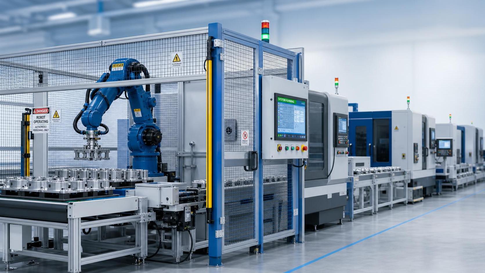
A CE certified handling robot should not reach European factory acceptance with only a CE mark, a cycle-time demonstration, and a generic certificate file. The decisive question is whether the delivered machine—or the complete robot cell—has been designed, assessed, validated, and documented as safe in its intended configuration.
For a handling robot, the most serious acceptance failures usually arise at the interfaces: the gripper, workpiece, infeed and outfeed equipment, perimeter guarding, manual loading positions, safety PLC logic, and any upstream or downstream machinery. A robot arm may be CE compliant as supplied by its manufacturer, while the integrated handling system is not yet ready for CE conformity assessment. European factory acceptance therefore needs to test the delivered safety concept, not merely the robot’s nominal performance.
It is also important to distinguish a CE declaration from a “CE certificate.” For most machinery, CE marking is based on the manufacturer’s conformity assessment, technical documentation, EU Declaration of Conformity, and application of the relevant legal requirements. Notified-body certification is not automatically required for every industrial robot installation. A document described commercially as a CE certificate does not replace the manufacturer’s legal responsibilities or prove that the particular delivered cell is compliant.
Define what is being accepted: robot, partly completed machinery, or complete cell
Acceptance can only be meaningful after the legal and technical scope has been fixed. A handling robot may be delivered in several very different forms:
- a robot arm with its controller and a manufacturer’s Declaration of Conformity;
- a robot supplied with an end effector but without safeguarding or integration into a production line;
- partly completed machinery, intended to be incorporated into a larger machine;
- a complete robot cell with fencing, interlocked access doors, controls, workpiece handling equipment, and defined operating modes;
- an integrated production system in which several suppliers provide machinery that operates as one functional whole.
This distinction determines who carries the final responsibility for the conformity of the assembly. When a robot, conveyor, gripper, welding station, loader, and guarding are combined so that they perform a common production function under coordinated control, the result may be an assembly of machinery. The party placing that completed assembly on the European market must establish the conformity of the whole, including hazards created by the interfaces.
Under the current transition framework, machinery placed on the market before 20 January 2027 is generally assessed under the Machinery Directive 2006/42/EC. Regulation (EU) 2023/1230 on machinery will apply from 20 January 2027. A factory acceptance file should identify the applicable legal framework and avoid mixing documentation assumptions from the Directive and the new Regulation without a clear applicability review.
The risk assessment must match the delivered application
EN ISO 12100 remains the core reference for machinery risk assessment: identify hazards, estimate and evaluate risks, then reduce risks through inherently safe design, safeguarding and complementary protective measures, followed by information for use. For handling robots, the risk assessment should be specific enough to answer a practical question: what can a person, tool, component, or unexpectedly released workpiece do in every operating mode?
A credible risk assessment cannot stop at “robot collision.” It should address foreseeable tasks and fault conditions, including:
- automatic pick-and-place movement, acceleration, braking, and restart after interruption;
- loss of vacuum, pneumatic pressure, electrical power, or gripper feedback;
- incorrectly positioned, oversized, damaged, or partially gripped workpieces;
- sharp edges, hot parts, unstable loads, and load shift during robot motion;
- access for loading, unloading, teaching, cleaning, adjustment, maintenance, and fault recovery;
- unexpected start-up after safety device reset, mode change, program selection, or communication recovery;
- interaction with conveyors, turntables, presses, welding equipment, pallet stations, or other moving machinery.
The declared payload of the robot is not, by itself, enough. The assessment must consider the combined mass, centre of gravity, inertia, gripping force, workpiece geometry, and the consequences of a dropped or ejected load. A robot that can technically lift a component may still require lower operating speed, additional mechanical retention, or a revised guarded zone if loss of the component creates an unacceptable hazard.
Where the robot is associated with a welding line, hazards can extend beyond motion. For example, when a robot transfers cylindrical shells to or from a Longitudinal seam welding machine, the safety review should include hot surfaces, clamping release, sharp sheet edges, weld spatter, fume extraction interfaces, and the possibility that a partly formed workpiece deforms or shifts. The robot cell and welding machine may have separate declarations, but their combined sequence must still be assessed where the interface creates a new hazard.
Guarding is not acceptable until access, distance, and stopping performance agree
Physical guarding must be judged as a system rather than as fencing purchased to a standard height. Perimeter guards, fixed panels, interlocked gates, presence-sensing devices, muting arrangements, and safety distances must correspond to the actual hazards and stopping characteristics of the cell.
Relevant standards commonly considered include EN ISO 14120 for guards, EN ISO 14119 for interlocking devices associated with guards, and EN ISO 13857 for safety distances. Their use does not remove the need to verify the actual installation. A gap below a fence, a reach-over route near an elevated robot position, or an opening around a conveyor can defeat an otherwise sound design.
Stopping distance is particularly important. The necessary safety distance for a light curtain, laser scanner, or other presence-sensing safeguard depends on the total time from detection to cessation of hazardous motion. That total includes sensor response, safety logic processing, communication delay where relevant, robot or drive stopping time, and any residual hazardous movement. The measured stop time must reflect the delivered payload, speed, program, and operating condition. A value taken from a robot catalogue or an unloaded demonstration does not validate the installed protective distance.
Guard-door tests should cover more than whether the robot stops. Opening an interlocked gate should initiate the required protective stop; closing it must not create an automatic restart; reset must be deliberate and located so that the protected area can be observed; and selection of automatic operation must not bypass unresolved access hazards. Where guard locking is used because a person could reach danger before movement has ceased, release timing and escape arrangements require close examination.
Safety functions need validation, not just a safety PLC specification
Robot-cell safety is often implemented through a safety PLC, safety-rated robot interfaces, safety relays, safe torque off functions, drive safety functions, interlock switches, emergency-stop circuits, and monitored valves. The safety-related control system must be designed to achieve the required risk reduction and then validated against its safety requirements.
EN ISO 13849-1 and EN ISO 13849-2 are widely used for the design and validation of safety-related parts of control systems. The key evidence is not merely a stated Performance Level. The technical file should show the safety functions, required performance level where the standard is used, subsystem assumptions, architecture, diagnostic coverage where applicable, calculations or manufacturer data, electrical schematics, software configuration control, and validation results.
Typical safety functions for a handling robot include:
- protective stop on gate opening or intrusion detection;
- prevention of unexpected restart after a protective stop;
- safe reduced speed and limited motion during teaching or setup;
- safe stop on loss of gripper-holding confirmation or critical pressure, where the risk assessment requires it;
- safe control of conveyors, turntables, clamps, and other auxiliary axes;
- emergency-stop initiation and controlled removal of hazardous energy where appropriate.
Emergency stop should be assessed under EN ISO 13850. It is a supplementary protective measure, not a substitute for guarded access or risk reduction by design. Emergency-stop devices must be readily accessible where needed, clearly identifiable, and functionally tested from every relevant location. They should not be treated as an acceptable means of routinely stopping a process for normal loading or maintenance.
For industrial robot applications, the relevant parts of the EN ISO 10218 series should be considered for the robot and robot application. Where a collaborative mode is claimed, the claim needs disciplined scrutiny. “Collaborative robot” does not mean that people may enter the working envelope without risk assessment or safeguarding. Tool geometry, handled load, pinch points, end-effector hazards, speed, force, and the surrounding process determine whether a collaborative application is actually safe. ISO/TS 15066 can provide useful guidance, but it does not make a specific installation compliant by itself.
Electrical compliance must be verified at the finished machine level
EN 60204-1 is commonly used for the electrical equipment of machinery. Acceptance should check the built control cabinet, field wiring, motors, sensors, safety circuits, disconnecting means, protective bonding, cable protection, identification, and documentation—not only the cabinet maker’s component list.
Points that frequently create avoidable corrective work include mismatched wire numbers and drawings, unlabelled terminals, missing protective-earth continuity evidence, incorrect conductor sizing, incomplete short-circuit protection information, unprotected cables at moving axes, and inadequate segregation between power and signal wiring. Where pneumatic or hydraulic energy is used, the corresponding energy isolation, residual-pressure release, valve behavior, hose routing, and maintenance safety arrangements also belong in the acceptance review.
The Machinery Directive or applicable machinery legislation is not the only possible legal instrument. Depending on the equipment supplied, EMC requirements, the RoHS Directive, the Radio Equipment Directive for wireless functions, and other applicable Union legislation may also need assessment. The correct approach is to identify applicable legislation from the actual product configuration and intended use, rather than assuming that one CE document covers all electrical and radio-related obligations.
Documentation should allow the delivered system to be reconstructed
A European factory acceptance should not close while the technical documentation remains generic, incomplete, or inconsistent with the machine in front of the inspection team. The technical file itself does not normally need to travel with every machine, but it must exist, be controlled, and support the conformity assessment. The customer should receive the documents required for safe installation, operation, maintenance, and integration.
The documentation package should normally include the final EU Declaration of Conformity for complete machinery, or a Declaration of Incorporation and assembly instructions where partly completed machinery is supplied. It should also include the machine identification details, final drawings and circuit diagrams, risk assessment, list of applied standards, relevant safety validation records, test reports, operating instructions, maintenance instructions, spare-part and consumable information where needed for safety, and declarations for incorporated equipment where relevant.
Instructions must correspond to the actual machine. This is where seemingly minor errors become serious: an emergency-stop location differs from the manual, a guard bypass procedure is described without controls, a tool-change task is omitted, or maintenance instructions do not explain stored energy and lockout requirements. For equipment intended for a particular European country, language obligations must be checked against the destination market. A technically accurate English manual is not automatically sufficient everywhere.
Factory acceptance should test foreseeable operating states, not a scripted production cycle
A smooth demonstration of automatic handling proves only that one sequence can run under controlled conditions. Acceptance testing should also include the conditions under which safety functions are expected to act. The test protocol should be traceable to the risk assessment and record test method, expected outcome, actual result, responsible person, and any corrective action.
Useful tests include each protective device and interlock, restart prevention, emergency stops, teaching-mode restrictions, manual recovery functions, mode selection, power-loss and power-restoration behavior, loss of pneumatic or vacuum supply, gripper status faults, access to trapped-person escape routes where relevant, and stop-time measurement where safeguarding distance depends on it. If production uses multiple workpiece sizes, tools, robot programs, or gripper configurations, the safety envelope must be checked for the permitted range rather than for a single favourable setup.
Any temporary bypass used during commissioning should be removed before handover, or controlled through a documented and risk-assessed maintenance procedure. A key switch alone is not a complete safety strategy. The purpose, access control, indication, duration, and operational limitations of any override must be defined.
The practical acceptance threshold is straightforward: the CE marking, declaration, risk assessment, safety functions, physical safeguards, electrical build, and instructions must all describe the same delivered handling robot system. When those elements disagree, the machine is not ready simply because it runs. Resolving the mismatch before shipment is far less disruptive than redesigning guarding, revising software, or rebuilding documentation after installation in Europe.
search
Products Navigation
Send Us A Message