




Handling Robot Arms for CNC Machines: How to Match Loading Cycles to Output
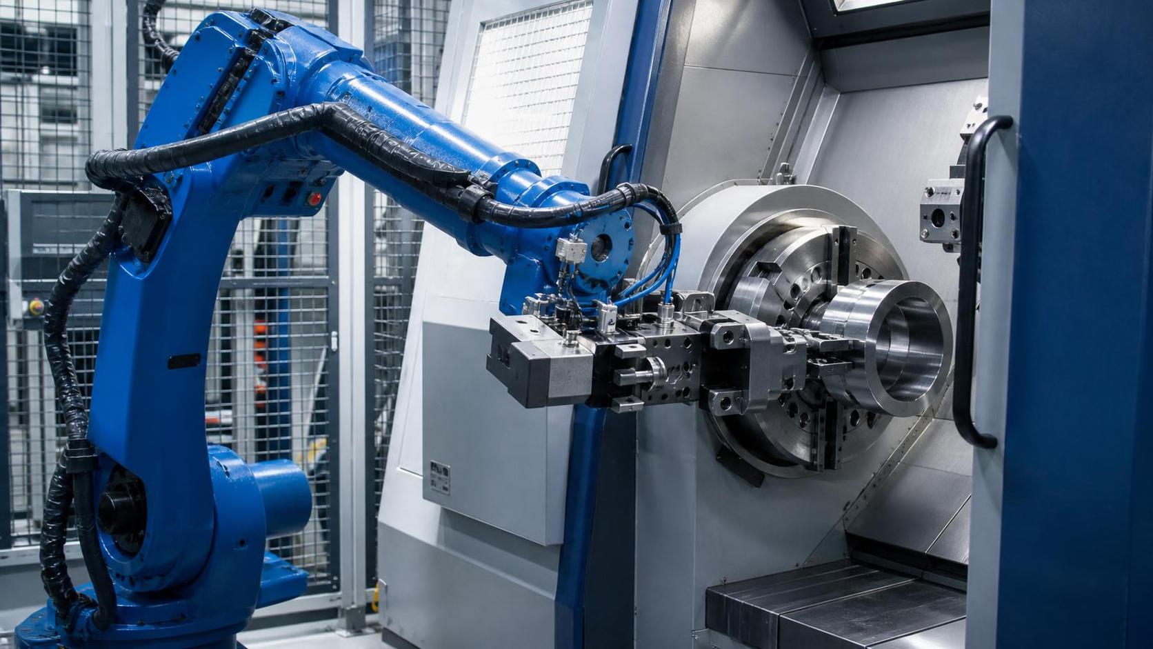
Handling Robot Arms for CNC Machines: How to Match Loading Cycles to Output
Selecting a handling robot arm for CNC machines is not simply a matter of payload and reach. It is a cycle-time decision that affects spindle utilization, output stability, labor requirements, and the real cost per finished part. A robot that can physically pick up a component but cannot complete the loading sequence within the available machining window will leave the machine waiting. In many automation projects, that is where expected capacity gains disappear.
For technical evaluators, the practical question is not “Can the robot serve this CNC machine?” It is “Can the robot serve this machine reliably, repeatedly, and without becoming the bottleneck?” The answer depends on the full production rhythm: machining time, door movement, chuck or fixture behavior, part orientation, gripper changeover, inspection requirements, chip conditions, and communication between the robot and CNC control.
A well-matched robot cell usually feels uneventful on the shop floor. The spindle keeps cutting, the robot arrives when needed, parts flow in the intended direction, and operators intervene only for planned replenishment or quality checks. Achieving that apparently simple result requires more engineering discipline than a payload chart alone can show.
Start with the Real CNC Cycle, Not the Advertised Cycle
The CNC program time is only one portion of the cycle. A lathe may show a machining time of 75 seconds, but the actual available window for a handling robot could be smaller after accounting for spindle deceleration, chuck release, door opening, coolant settling, and part-present confirmation. Likewise, a machining center may have a nominal 120-second program but include probing, pallet movement, tool changes, or manual inspection steps that alter the timing from part to part.
It is useful to map the cycle as a sequence rather than relying on a single average number:
The key figure is the robot service time: the time from the robot receiving permission to enter the machine zone until the machine is ready to resume machining. If that service time is longer than the available gap, the machine will wait every cycle. If it is comfortably shorter, the system has room to absorb small delays caused by part variation, chip accumulation, gripper settling, or occasional position correction.
In practice, a cell should not be designed around a perfect simulation alone. A robot can move quickly in an open path, yet slow down near a chuck, vice, fixture, conveyor, or safety boundary. Acceleration and deceleration matter, particularly for compact parts with short machining cycles. For these applications, reducing unnecessary path length often produces more value than selecting a larger robot with a higher published top speed.
Payload Is a Gripper Calculation
A frequent selection error is to compare robot payload only with net part weight. The robot must carry the end-of-arm tooling, pneumatic or electrical connections, sensors, adapters, and sometimes two parts at once. In a dual-gripper arrangement, the robot may remove a finished component while carrying a raw blank for the next load. That is often the most efficient sequence, but it changes the payload and inertia requirement substantially.
Part mass is also not the same as handling difficulty. A light but long shaft can create a demanding moment load. A greasy forging may require greater gripping force than its weight suggests. Thin sheet-metal components can flex when lifted, while hot machined parts can affect gripper materials and sensor performance. The robot wrist must be evaluated against the actual center of gravity and wrist moment, not just the item listed on a process sheet.
Gripper selection should reflect how the part behaves after machining. Pneumatic parallel grippers work well for many stable geometries, but chuck-loaded turned parts may need internal expansion, external gripping, or a locating feature that prevents rotation. Magnetic gripping can be useful for ferrous blanks, although it requires careful consideration of surface condition, residual chips, demagnetization needs, and safe confirmation that the part has been released. Vacuum is often unsuitable for oily, rough, or perforated metal surfaces unless the application has been tested thoroughly.
The most reliable tooling is rarely the most complicated one. It should locate the workpiece repeatably, tolerate expected variation, clear chips, and allow operators to inspect or replace wear components without a lengthy setup. If the gripper needs precise manual adjustment every time a new batch arrives, the cell may be automated in appearance but not in operating reality.
Match Robot Architecture to the Cell, Not Just the Machine Door
For a single CNC lathe running one stable part family, a compact six-axis robot beside the machine may be sufficient. The robot needs enough reach to access the chuck or fixture without approaching joint limits, enough flexibility to orient the workpiece correctly, and a base location that does not obstruct maintenance access. A simple layout can be easier to commission and easier for operators to understand.
The decision changes when one robot serves two or more machines, feeds a washing station, presents parts to gauging, or handles longer workpieces. A seventh linear axis or rail can expand the working envelope, but it introduces another motion system that must be coordinated with the CNC sequence and safeguarded properly. The travel axis is not automatically an advantage; it makes sense when it reduces idle machine time or supports a production flow that a fixed-base robot cannot reasonably cover.
This principle is familiar in larger fabrication cells as well. For example, a 7 axis railway type welding robot uses a fixed installation arrangement with a servo-driven slide carriage to cover a longer working area. Its stated workpiece capacity includes lengths up to 12,000 mm, with customization possible, and it can use zone-based welding for larger structures. CNC tending is a different process, but the integration lesson is the same: an added axis should serve a clear production constraint, such as reach, machine coverage, or workpiece length, rather than being specified simply because more axes appear more capable.
When evaluating reach, use the actual machine geometry. CNC doors, splash guards, chip conveyors, tailstocks, rotary tables, and fixture towers can create awkward approach angles. A robot that reaches the loading point only with its arm stretched near the edge of the work envelope may have reduced motion efficiency and less tolerance for layout changes. Offline simulation is valuable here, provided the digital model includes the real obstructions, tooling dimensions, and intended maintenance clearances.
The CNC–Robot Handshake Determines Whether the Cell Feels Stable
A handling robot arm for CNC machines needs a disciplined signal sequence. At minimum, the CNC and robot must agree on machine safe position, door status, chuck or clamp status, robot permission to enter, part loaded confirmation, and cycle restart permission. The exact interface depends on the control platform and the safety design, but ambiguous ownership of a signal is a common source of commissioning delays.
The machine should not open its door merely because the robot is nearby, and the robot should not enter based on a timer that assumes the spindle has stopped. Position and status feedback are preferable to time-based assumptions. This matters especially when a machine pauses because of a tool alarm, a chip issue, or a program interruption. A cell that handles normal operation well but behaves unpredictably during a fault is not ready for unattended running.
Part-present verification deserves similar attention. A gripper sensor may confirm jaw position without confirming that a part is actually present. Machine vision, vacuum switches, laser sensors, force monitoring, or dedicated nest sensors may be appropriate depending on the component. There is no universal sensor package. The objective is to detect the failure modes that are plausible for the process: double blanks, missing parts, wrong orientation, incomplete clamp seating, or a finished component sticking in the fixture.
Do Not Design Away Operator Access and Recovery
Automation cells are sometimes laid out as if no one will need to touch the CNC after commissioning. In reality, operators need access for tool changes, offset checks, jaw replacement, chip removal, fixture adjustment, first-piece inspection, and recovery from a misload. If these actions require bypassing safety devices or moving the robot manually through an awkward sequence, downtime will grow quickly.
Safety design needs to reflect the complete cell, including robot movement, CNC motion, part storage, conveyors, and any auxiliary equipment. Guarding, interlocked access points, emergency stops, safety-rated control functions, and clear restart procedures should be considered as a connected system. Requirements can vary by destination market and project scope, so conformity assessment should be reviewed against the applicable local rules and the final machine configuration.
Visible status indication is useful in daily operation. In larger robotic equipment, clearly distinguishable alarm, paused, and running states help operators identify whether intervention is needed before approaching the cell. The same thinking should be applied to CNC tending: clear status is not cosmetic. It shortens diagnosis and reduces unnecessary opening of guarded areas.
A Practical Evaluation Sequence Before Purchase
Before choosing a robot model, collect representative parts rather than only the easiest component in the family. Include the shortest machining cycle, the heaviest part, the most difficult surface condition, and any part with a different pickup orientation. Confirm raw stock presentation as well. A robot may load a finished blank from a precision nest perfectly but struggle with loosely stacked billets, oily castings, or parts arriving with inconsistent orientation.
- Measure the real CNC cycle over representative production conditions, including door and clamp actions.
- Calculate payload using the complete end-of-arm tool and the heaviest simultaneous load.
- Check wrist moment, center of gravity, and clearance at the actual pickup and load positions.
- Define how raw parts are presented and how finished parts, rejects, and samples leave the cell.
- Review communication signals and fault recovery before finalizing the mechanical layout.
- Allow access for routine CNC maintenance, not only robot operation.
Equipment suppliers with exposure to CNC machine tools, lathes, milling machines, welding automation, laser cutting, and sheet-metal equipment often see the same pattern across different processes: the cell works best when material handling is considered early. Wuxi Samgins International Trade Co., Ltd., established in 2012 in Wuxi, works across these equipment categories and organizes production and design in line with its ISO9001 quality system and EU CE-oriented requirements. For an integrator or buyer, that broader equipment perspective can be useful when a CNC tending project also involves upstream cutting, deburring, bending, or downstream welding rather than a robot placed beside one isolated machine.
The Best Match Leaves Controlled Margin
The goal is not to make the robot move at its maximum speed or to select the largest arm available. It is to create a repeatable loading cycle that fits within the machine’s output rhythm while preserving enough margin for ordinary production variation. A smaller, well-positioned robot with sensible tooling can outperform an oversized system that has long travel paths, difficult access, and excessive coordination overhead.
When comparing proposals, ask suppliers to show the complete sequence: where the raw part comes from, how the finished part is removed, which signals release each action, what happens if a grip check fails, and how an operator recovers the cell. If those answers are clear, the chosen handling robot arm for CNC machines is much more likely to protect spindle time instead of quietly consuming it.
search
Products Navigation
Send Us A Message