




Choosing a Handling Robot Arm for Press Brakes: Payload, Reach, and Safety
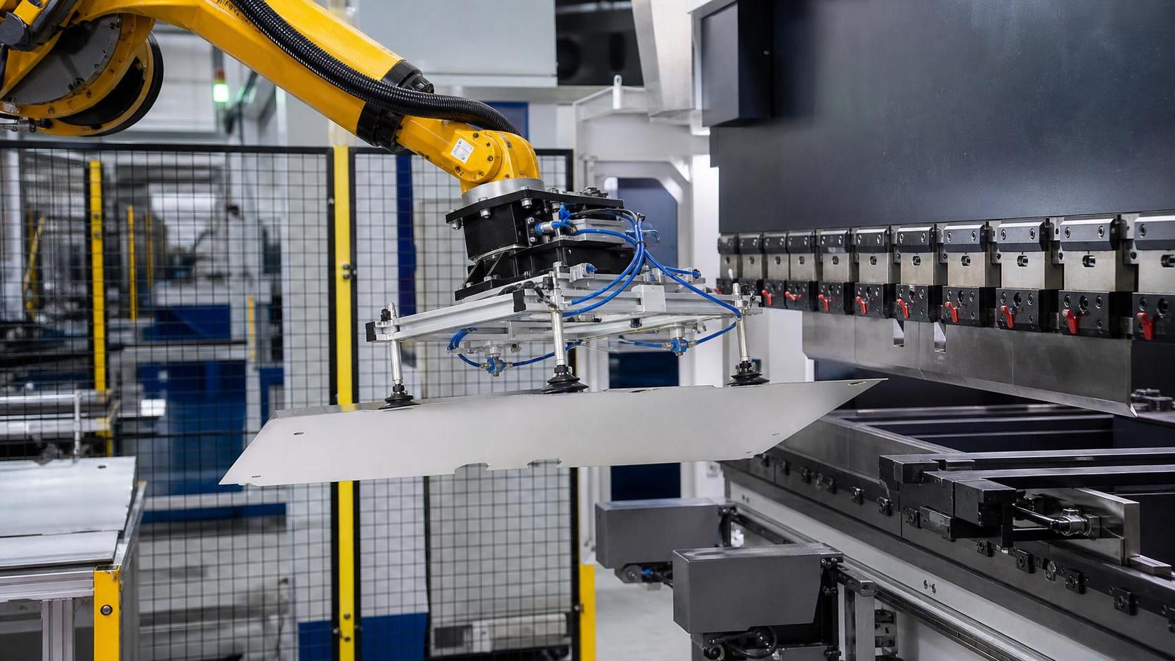
A handling robot arm for press brakes should be selected from the part outward, not from the robot catalogue inward. The first questions are: what must the robot pick, where must it place the part during every bend, and how will the cell remain safe when a sheet is misaligned, flexes, or changes between jobs?
Payload, reach, and safety are the visible specifications, but they only work as a decision framework when evaluated together with gripper mass, part geometry, press brake tooling, production mix, and material flow. A robot that can lift the nominal part weight may still be unsuitable if its wrist torque is exceeded by a long panel, its reach forces an awkward mounting position, or its gripper cannot control a flexible blank through the bend sequence.
Start with the workpiece family, not a single “maximum” part
Build the evaluation around representative parts: the smallest and largest blanks, the heaviest sheets, the longest panels, narrow strips, perforated material, polished surfaces, and parts with return flanges. The robot must handle the full approved range without compromising repeatability or introducing unsafe manual intervention.
A useful part profile includes material type and thickness, blank length and width, mass, center of gravity, surface condition, hole patterns, allowable marking, bend sequence, final part shape, and expected batch size. This reveals whether the process calls for a conventional industrial robot, a rail-mounted robot, a gantry arrangement, a dedicated loading system, or a different automation concept altogether.
Do not assume that a robot suitable for loading flat blanks will also handle the formed part. As bends accumulate, the center of gravity shifts and the occupied envelope becomes much larger. A shallow tray may be easy to support, while a long channel or box section can create collision and wrist-load problems even when its actual mass is modest.
Calculate payload as a complete end-of-arm load
Robot payload is not the sheet weight alone. It must include the gripper body, vacuum cups or magnetic modules, valves, sensors, brackets, cable routing, and any tool changer. The center of gravity of this complete assembly matters as much as the total mass.
Long sheet-metal parts are particularly demanding because distance from the wrist magnifies the turning load. A robot may remain within its stated payload while approaching a wrist moment or inertia limit during fast rotation, acceleration, or emergency stopping. This is why a simple “part weight plus gripper weight” calculation often produces an optimistic selection.
Evaluate payload in the actual poses required by the bend program. The critical condition may occur while the robot holds a wide blank horizontally, rotates a partially formed part near the die, or presents a tall return flange to the press brake. Include the worst practical gripper configuration, rather than using the lightest tool proposed for a demonstration.
Oversizing a robot can provide useful margin, but it is not automatically the best outcome. A larger robot may occupy more floor space, require a larger safety envelope, and move less efficiently on smaller parts. The appropriate margin is the one that covers real tooling and dynamics without making the cell unnecessarily difficult to integrate.
Reach must be checked against the full bending envelope
Catalogue reach is usually measured to a point in a favorable pose. It does not prove that the robot can pick from the loading station, align at the backgauge, support the sheet during bending, rotate the formed part, and place it on the unloading side without singularities or collisions.
The press brake itself creates a complex access zone. Tool height, die opening, ram travel, backgauge position, front support arms, workpiece growth after bending, and nearby conveyors all affect motion planning. A robot positioned close to the brake may reach the bend line easily but have insufficient room to rotate a formed component. Placing it farther away can solve clearance issues while creating a reach or cycle-time penalty.
Check the difficult poses before reviewing speed
Ask for a simulated cycle using actual part models and realistic tooling. The simulation should include approach, pickup, inspection or centering if used, loading, every repositioning movement, bending clearance, discharge, and recovery poses. It should also show the robot’s joint configuration. A motion that is technically reachable but close to a singularity may be slow, unstable, or difficult to maintain when part variation occurs.
For long or flexible panels, two robots or a robot combined with a support device can be more practical than one oversized arm. The objective is not simply to lift the sheet; it is to hold the bend line accurately while preventing sag, twist, and uncontrolled movement. The correct support arrangement depends on blank dimensions, material stiffness, bend orientation, and the number of regrips required.
The gripper often decides whether automation is viable
Gripper selection should begin with the material and part condition. Vacuum gripping is flexible for many flat sheet applications, but porous surfaces, perforations, oily sheets, warped blanks, and very small contact areas require careful validation. Magnetic gripping can suit ferrous materials but needs different safeguards for residual magnetism, stacked sheets, and varying contact conditions. Mechanical grippers may provide positive restraint, although they can require accessible edges and can interfere with formed flanges.
A press brake robot usually needs more than reliable pickup. It may need to separate blanks from a stack, detect double sheets, center the workpiece, compensate for minor position variation, hold the part while the ram closes, and change grip points between bends. These functions should be considered as one handling strategy, not as optional accessories added after the robot is chosen.
Part variation is a common dividing line. A stable family of similar components supports a simpler, faster cell. High-mix work involving different blank sizes, flange shapes, surface finishes, and bend sequences requires adaptable grippers, reliable recipe control, and changeover discipline. Automation can still make sense, but the justification should account for engineering time and operational complexity, not only direct labor removal.
Cycle time is a cell result, not a robot specification
Fast robot axes do not guarantee a fast bending cell. The robot must synchronize with the press brake, loading equipment, gripper actions, part measurement where applicable, and unloading method. The brake may be waiting for the robot, or the robot may be waiting for ram completion, backgauge movement, or a safe access signal.
Break the target cycle into steps and identify the limiting one. Pay particular attention to blank separation, first-part alignment, regrips, rotations of large formed parts, and discharge. A cycle estimate that only measures travel between two points usually excludes the activities that make real production slower.
It is also sensible to distinguish between average speed and reliable speed. A cell that achieves a short demonstration cycle but loses time to vacuum faults, part slipping, stack separation errors, or frequent manual resets will not deliver predictable output. The better design is often the one with slightly less aggressive motion but clearer part control and easier recovery.
Safety is part of the mechanical layout
A robotized press brake requires a safety concept that covers normal automatic operation, setup, manual jog, maintenance, fault recovery, and material replenishment. Treating safety as a final guarding exercise can leave poor access, excessive reset locations, and unclear responsibilities between the robot controller and press brake controls.
The assessment should define all hazard zones: robot sweep, gripper and sheet movement, press brake tooling area, loading and unloading stations, stack handling, and pinch points around conveyors or support devices. Long sheets create a moving hazard beyond the robot wrist because their corners and edges can sweep through a wide area during rotation.
- Confirm how the robot and press brake exchange permissive and safe-stop signals.
- Verify that protective devices match the actual material path, including part overhang.
- Provide a practical setup mode with reduced-speed operation and clear operator visibility.
- Plan how a dropped, skewed, or partially bent part will be removed without entering an uncontrolled area.
- Place controls, reset devices, and loading positions so routine work does not invite bypassing safeguards.
Recovery deserves specific attention. In production, sheets can be skewed, vacuum can fail, a formed part can catch on a tool, or an operator may need to clear a jam. The best cell designs establish controlled recovery positions and sequences in advance. This reduces both downtime and the temptation to improvise around equipment that is still energized.
When the handling problem is larger than the press brake cell
Not every handling challenge belongs on the robot arm. Large structural workpieces may need separate turning and positioning equipment before or after fabrication operations. For example, an H-beam production line handling long, heavy sections may use a chain turnover system to rotate a workpiece into an accessible welding position. A solution such as the H beam Chain turnover machine is intended for that different handling task, with synchronized turnover arrangements available for long workpieces. It should not be treated as a substitute for a press brake robot; it addresses large-workpiece rotation rather than programmed sheet-metal loading and bending support.
This distinction matters during line planning. A press brake automation project performs best when upstream blank preparation, downstream stacking, and any heavy-part turning are assigned to equipment designed for their respective loads and motions. Trying to make one robot solve every material-handling problem usually increases cost and reduces robustness.
A practical selection sequence
- Define the approved part family and identify the largest, heaviest, longest, most flexible, and most difficult-to-grip parts.
- Specify the complete end effector, including all accessories, and evaluate mass, center of gravity, torque, and inertia in working poses.
- Model the full cell with real press brake tooling, loading, unloading, and formed-part envelopes.
- Test the proposed gripping method on representative materials, finishes, perforations, and stack conditions.
- Review the bend sequence to identify regrips, support requirements, collision risks, and cycle-time constraints.
- Develop the safety and recovery concept alongside the layout, controls interface, and operator workflow.
- Use an acceptance plan based on representative parts and normal production conditions, not only one favorable demonstration piece.
The strongest choice is rarely the robot with the highest listed payload or longest nominal reach. It is the handling system that maintains control of the actual part family, reaches every required pose without marginal geometry, fits the press brake process, and allows operators to run, load, and recover the cell safely.
search
Products Navigation
Send Us A Message