




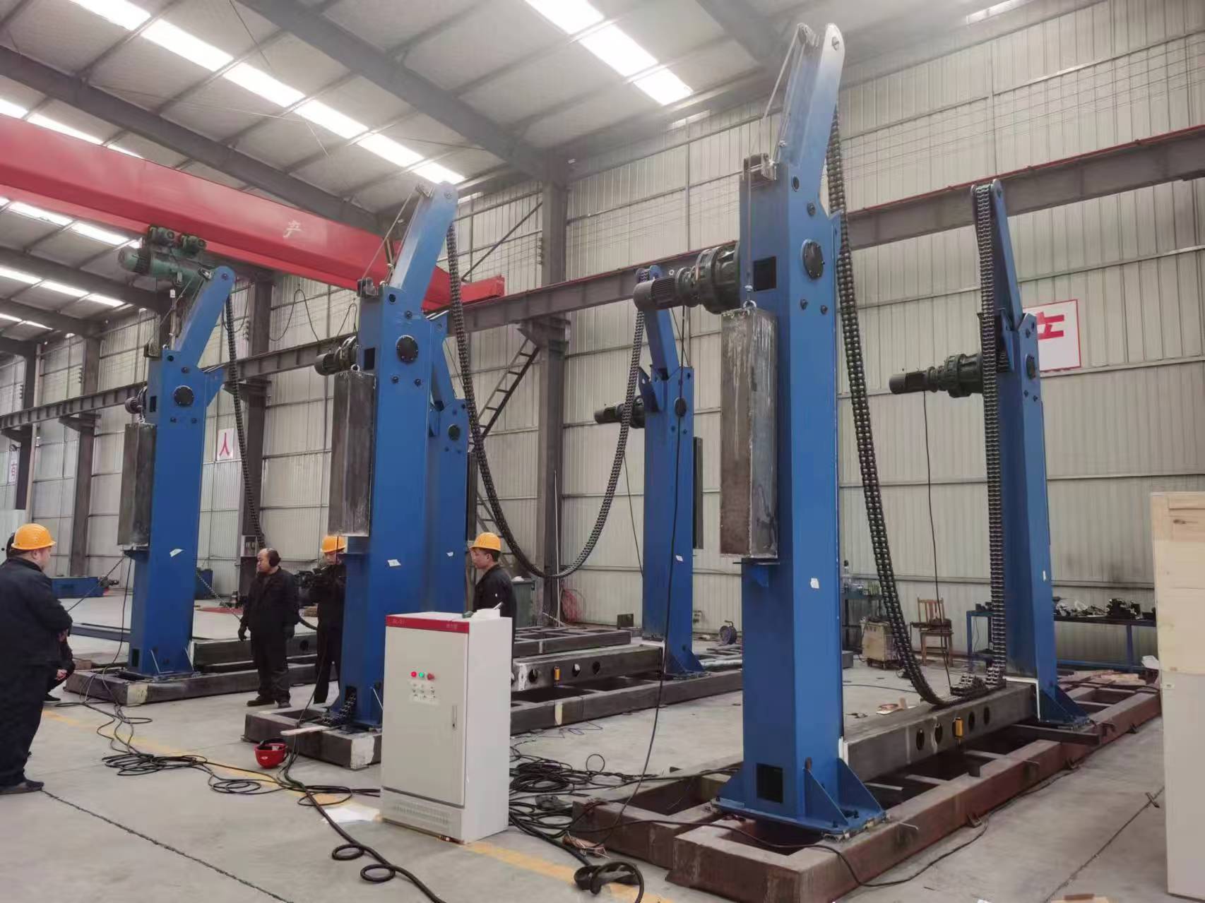
H beam Chain turnover machine
Full-range Machinery & Customized Non-standard Solutions
Authorized Certificates & Independent R&D Patents
Over 10 Years Global Export & Worldwide Project Cases
Navigation

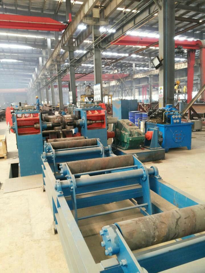
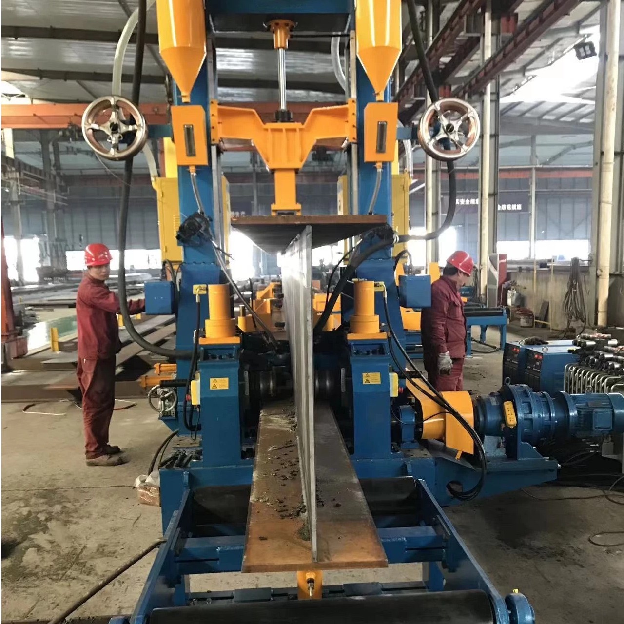
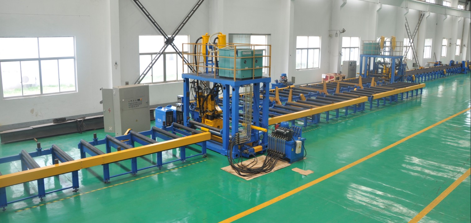
H beam Chain turnover machine Description
1.Introduction for H beam Chain turnover machine:
1.1 Equipment Overview and Function
The flipping tires are designed to rotate products through 360 degrees for positional adjustment. The equipment features an inverted gantry‑type structure and is equipped with four reducers to control the workpiece, offering convenient operation during the flipping process.
1.2 System Composition
The flipping tires consist of swing arms, support columns, reset devices, and an electrical control and operating system. The assembly also includes four standing columns, each fitted with a driving mechanism on the top. A brake motor controls the cycloidal pinwheel reducer, which in turn drives the sprockets.
1.3 Drive and Guidance Mechanism
Each sprocket is equipped with two pulleys mounted on the swing arm. One pulley serves to change the direction of chain movement and to extend the chain travel. A guide wheel is positioned near the bottom of the sprocket to increase the chain wrap angle on the sprocket, ensuring positive engagement.
2.Technical parameter for H beam Chain turnover machine
3.Characters for H beam Chain turnover machine:
3.1 Workpiece Capacity
This equipment is specifically designed to handle large, long‑shaped workpieces, particularly H‑beams and other extremely long and heavy components. It accommodates a maximum cross‑sectional size of 3,800 × 3,800 mm, with a length range typically between 7,000 and 14,000 mm, and a maximum load capacity of up to 15,000 kg.
3.2 Full‑Angle Flexible Rotation
A chain drive mechanism enables 360° continuous rotation of the workpiece at any angle. By adjusting the motor drive direction, the two supporting chains move synchronously to complete the rotation action. This feature allows the longitudinal weld seam to be quickly repositioned to the flat welding position, significantly reducing operator labor intensity while ensuring consistent weld quality.
3.3 Lifting and Stabilization Control
In addition to flipping, the equipment is equipped with lifting and lowering functions. For extremely long workpieces, a head‑tail frame synchronous flipping machine design can be adopted, with multiple powered flipping units connected in series and rotating in synchronization with driven units. This effectively prevents workpiece oscillation during flipping, ensuring stability and safety throughout the welding process.
3.4 Drive and Control System
The drive system typically employs a combination of a cone brake motor and a cycloidal pinwheel reducer, with a total installed power of up to 9 kW. Control is primarily achieved via remote operation, facilitating safe long‑distance handling.
3.5 Structural Design Features
The typical structure consists of four columns, each with a swing arm mounted at the top and equipped with a motor and reducer. The carrying chain is an open‑type chain that wraps around the columns and the sprockets of the swing arms. This design has inherent limitations: larger cross‑sectional workpieces require longer carrying chains and taller columns, which in turn increases the demands on equipment strength and stability.
products faq
An H Beam Production Line is a complete automated system for manufacturing H-shaped steel beams. It typically includes an uncoiler, leveling unit, assembly machine, tack welding machine, main submerged arc welding (SAW) system, straightening machine, cutting equipment, and material handling conveyors. All components work together to transform steel plates or coils into finished H-beams with high efficiency and consistent quality.
Submerged Arc Welding (SAW) is the most commonly used process for main welding in H beam production lines. It offers deep penetration, high deposition rates, excellent weld quality, and minimal spatter—making it ideal for heavy structural beams. Some lines also incorporate gas-shielded welding for tacking or light sections.
The line is adjustable to accommodate a wide range of beam sizes. Standard configurations typically handle web heights from 200mm to 1,500mm, flange widths from 100mm to 800mm, and material thicknesses from 6mm to 60mm. Custom sizes can be accommodated with tailored equipment design.
After welding, the thermal distortion caused by heat input is corrected by a straightening machine, which applies pressure to bend the beam back to the required straightness tolerance. In addition, precision assembly fixtures and automated control systems ensure accurate web-flange positioning before welding, maintaining consistent product dimensions throughout production.
Routine maintenance includes checking and replacing welding consumables (flux, wire, contact tips); inspecting conveyor chains, rollers, and bearings; monitoring hydraulic system oil levels and seals; cleaning the flux recovery system; and verifying the straightening machine's adjustment accuracy. We provide comprehensive maintenance schedules, spare parts support, and on-site technical assistance to minimize downtime.