




How do laser tracking systems improve repeatability in automatic space frame welding machine operations?
How do laser tracking systems improve repeatability in automatic space frame welding machine operations?
Sep 27, 2026
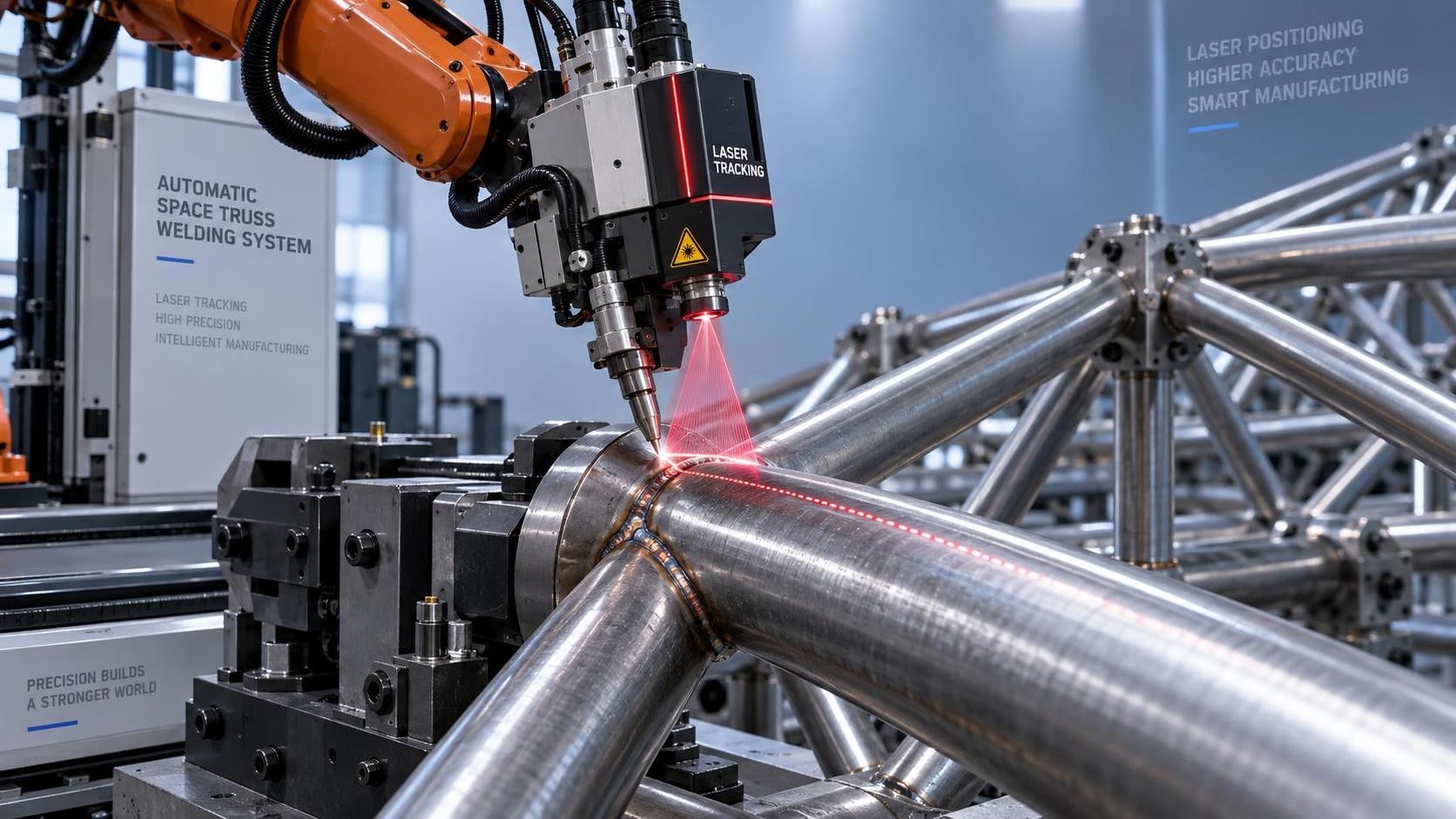
Laser tracking systems do not merely add measurement capability to automatic space frame welding machines—they redefine how repeatability is achieved in practice. For operators, repeatability isn’t about theoretical robot path accuracy alone; it’s the consistent delivery of weld geometry, penetration depth, and joint alignment across dozens or hundreds of identical frames—despite thermal distortion, fixture wear, part-to-part dimensional variation, and ambient shop-floor conditions. Laser tracking addresses this by closing the loop between commanded motion and actual workpiece position—not before welding starts, but *during* the process.
At its core, laser tracking replaces static teach-point programming with dynamic, real-time spatial feedback. A Class 2 or Class 3R laser sensor mounted on the welding head (or adjacent gantry) projects a structured light pattern onto the joint surface. As the robot moves, the system continuously triangulates the exact 3D coordinates of the seam centerline—typically at 1–5 kHz sampling rates—with sub-0.1 mm resolution. This data feeds directly into the motion controller, which adjusts axis trajectories on-the-fly to maintain torch-to-joint offset within tolerance. The result is not just tighter positional control—it’s adaptive compensation for deviations that would otherwise accumulate across multi-pass welds or long traverses.
This matters most where geometry complexity meets production reality. Space frames consist of intersecting tubular members—often with variable wall thicknesses, inconsistent bevel angles, and minor misalignments introduced during manual loading or fixture settling. Without tracking, even a robot with ±0.08 mm repeatability (like the Multipurpose Handing Robot BR10iB-15) cannot guarantee repeatable weld quality if the reference coordinate system drifts relative to the actual joint location. Laser tracking decouples repeatability from fixture fidelity: it makes the machine respond to what is physically present—not what was programmed.
Thermal expansion introduces another layer of deviation. In aluminum or thin-walled steel frames, localized heating can shift joint position by 0.2–0.5 mm over a single pass. Open-loop systems treat this as noise—compensated only through conservative parameter margins or post-weld correction. Laser tracking treats it as signal: the system detects the drift mid-weld and recalculates trajectory in real time. Operators report significantly fewer instances of undercut, incomplete fusion, or excessive spatter—especially at T- and K-joints where heat buildup is asymmetric and joint geometry shifts rapidly.
Crucially, laser tracking does not require reprogramming for each new frame variant. Once calibrated to the base coordinate system of the welding station, it adapts to any part within its field of view. This eliminates one of the largest sources of operator error: reliance on manual touch-up or “teach-and-repeat” corrections when switching between similar but non-identical parts. It also reduces dependency on high-cost, high-precision fixtures—lowering setup time and enabling faster changeovers without sacrificing weld consistency.
But implementation is not plug-and-play. Effective tracking depends on three interdependent factors: optical access, surface condition, and integration architecture. The laser must maintain line-of-sight to the joint throughout the entire weld cycle—even during complex multi-axis motions. Obstructions from tooling, clamps, or the workpiece itself force careful sensor placement and sometimes necessitate multiple sensors per station. Surface reflectivity matters: bare, mill-finished steel works reliably; heavily oxidized, painted, or oily surfaces degrade signal integrity and may require pre-weld cleaning protocols. Integration requires tight synchronization between the laser controller, robot motion controller, and power source—ideally via EtherCAT or PROFINET—not just RS-232 bridging. Delays longer than 10 ms in feedback loop timing introduce lag-induced oscillation, undermining repeatability rather than improving it.
Operators also need to understand what laser tracking *does not* compensate for. It cannot correct gross positioning errors—such as a tube loaded 2 mm off-center in the fixture—or compensate for incorrect weld parameters (voltage, wire feed speed, travel rate). Its role is geometric correction, not process parameter optimization. Misinterpreting its function leads to overconfidence: assuming tracking will “fix” poor joint fit-up or unstable arc conditions. In practice, tracking amplifies the value of good upstream preparation—it doesn’t replace it.
From a maintenance perspective, laser tracking adds a calibrated optical subsystem to the machine’s critical path. Sensors require periodic verification against traceable artifacts—typically using certified gauge blocks or step gauges—and lens cleaning after every shift in dusty environments. Unlike mechanical encoders, laser systems are sensitive to ambient light interference; direct sunlight or intense arc glare can saturate detectors unless properly shielded or filtered. Operators trained only on conventional robotic welding often underestimate these operational constraints—leading to unplanned downtime if calibration drift goes undetected for more than 48 hours.
The impact on repeatability metrics is measurable—but not uniform across all weld types. For fillet welds on flat seams, tracking typically improves positional repeatability from ±0.3 mm (open-loop) to ±0.07 mm. For circumferential welds on round tubes, where joint curvature and torch angle interact dynamically, improvement is less pronounced—±0.12 mm vs. ±0.25 mm—because laser triangulation accuracy degrades slightly at steep incidence angles. These differences matter when qualifying welds to ISO 15614 or AWS D1.1: operators must validate tracking performance under the specific joint configuration and material combination being welded—not just on test plates.
Finally, repeatability gains translate directly into downstream process reliability. When weld geometry stays within 0.15 mm of nominal across 100 consecutive frames, downstream assembly—especially robotic fitting or automated bolting—experiences far fewer fit-up failures. Scrap rates drop not because defects are eliminated entirely, but because variation is contained within statistical control limits. That allows operators to shift focus from reactive correction to proactive monitoring: reviewing tracking logs for subtle trends—like gradual fixture wear signaled by increasing positional correction magnitude—before they trigger nonconformance.
In summary, laser tracking improves repeatability not by making robots more precise in isolation, but by anchoring their motion to the actual workpiece—continuously, adaptively, and with metrological rigor. It transforms repeatability from a static specification into a live, verifiable process metric—one that operators can monitor, trend, and act upon in real time. For those running automatic space frame welding machines, that distinction separates consistent output from conditional consistency.
search
Products Navigation
Send Us A Message