




Machine Loading Robot Arms Explained: Grippers, Positioning, and Cycle Control
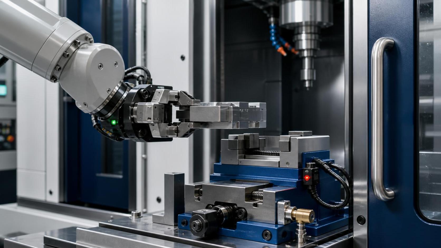
A machine tending cell can look straightforward on a layout drawing: a robot picks a blank, opens the machine door, loads the fixture, starts the cycle, then removes the finished part. In production, the difficult moments occur at the handoff points. A gripper may hold a part securely but fail to clear a vise jaw. A robot may repeat its taught position accurately while the workpiece still lands inconsistently because the stock is warped, oily, or not seated against a locating stop. A fast robot path may save little time when the CNC cycle, door movement, chuck response, and part-present signals are poorly coordinated.
The core evaluation rule is simple: a machine loading robot arm is reliable only when the gripper, part location method, robot motion, machine interface, and recovery logic are designed as one controlled sequence. Robot repeatability alone does not guarantee loading accuracy. The technical review should begin with the actual part condition and machine-loading geometry, then verify whether payload, reach, end-of-arm tooling, positioning references, and cycle control can maintain that sequence without operator intervention.
Start with the loading event, not the robot catalogue
Before comparing robot models, define what must happen during each machine cycle. This is more specific than stating that the application is “CNC loading.” The robot may need to pick a raw casting from a pallet, orient it, clear a guarding opening, place it against a fixture datum, wait for clamping confirmation, and then retrieve the finished part from a hot or wet machining environment. Each action creates a separate technical requirement.
A useful first review is to map the part from incoming condition to outgoing condition. Note whether the robot handles raw stock, partially machined parts, finished components, or multiple workpieces at once. Identify the gripping surface before and after machining. A turned diameter may be available before machining but disappear after a secondary operation. A flat face may be suitable for a vacuum cup when dry but unsuitable once coolant residue is present. This analysis often changes the end-effector concept more than it changes the robot selection.
The machine itself also determines the cell architecture. Door opening width, chuck or vise position, fixture height, access from the front or side, allowable robot approach angles, and clearance above the workholding all affect the required robot envelope. A robot with sufficient nominal reach can still be unsuitable if its wrist cannot enter the machine at the required orientation without passing close to guards, probes, or spindle components.
Gripper design: secure retention is only the first requirement
Gripper selection should be based on the full part-handling condition rather than part weight alone. The end effector must retain the workpiece during acceleration, deceleration, wrist rotation, and any unexpected stop permitted by the safety configuration. It must also tolerate realistic variation in material surface, oil, burrs, temperature, and incoming dimensions.
Match the gripping principle to the part and process
Mechanical parallel grippers are commonly used where stable outside or inside surfaces are available. They can provide positive retention and are often appropriate for machined billets, shafts, rings, and prismatic parts. Jaw geometry should avoid contacting critical finished surfaces, and the jaw stroke must accommodate incoming part variation without allowing excessive radial movement.
Three-jaw or centric grippers can improve centering for round components, but their practical repeatability depends on jaw wear, part diameter consistency, and whether the part seats against a defined axial reference. For parts transferred between a lathe chuck and a loading gripper, engineers should examine whether the gripping datum is the same in both devices. A part held from an unfinished outside diameter may shift slightly after a machining operation changes that diameter.
Vacuum tooling can be effective for sheet, flat blanks, and nonporous parts, yet it requires careful review in machining cells. Surface contamination, holes, rough casting skins, coolant, and porosity can reduce holding force. Vacuum sensing should be used as a process confirmation signal, not merely as an indication that a pump is running. Magnetic grippers can suit ferrous components but require consideration of residual chips, demagnetization needs, and the effect of part geometry on holding force.
For complex or mixed-family parts, a dedicated gripper with interchangeable fingers may be more reliable than a highly general-purpose tool. The trade-off is changeover effort. Where frequent variants are expected, quick-change tooling, coded gripper identification, and recipe-controlled jaw positions can reduce the risk of loading the wrong tool for the selected program.
Calculate the real wrist load
Robot payload is not simply the mass of the workpiece. The evaluation must include the gripper body, fingers, brackets, pneumatic valves, sensors, cable dress, and any dual-grip arrangement. The robot wrist also experiences a moment load determined by the distance between its mounting flange and the combined center of gravity. A light part held far from the wrist can create a more demanding dynamic condition than a heavier part held close to it.
Payload reserve is especially important when the robot carries both a finished part and a raw blank during a swap. In many machine-tending sequences, this dual-part transfer is used to reduce idle time at the machine. It improves cycle efficiency only if the combined mass, center of gravity, and clearance conditions remain within the robot and gripper limits throughout the motion path.
Positioning accuracy comes from the datum chain
A common misunderstanding is to compare robot repeatability directly with machining tolerance. These values describe different things. Robot repeatability indicates how consistently the robot returns to a taught position under stated conditions. It does not include gripper deflection, part variation, fixture wear, pallet position error, machine-door movement, or a part that is only partially seated against a stop.
In a robust cell, the robot transfers the part to a machine-side locating system that establishes the machining datum. The robot should not be expected to “place accurately in free space” and rely on clamp force to correct every error. A lead-in chamfer, tapered locator, nest, hard stop, or guided loading feature can absorb small approach deviations while ensuring that the part reaches the same final reference position.
Consider a CNC vise loading operation. The robot approaches with the part aligned to the open jaws, lowers or advances to a controlled insertion point, pushes the workpiece against a fixed stop, and waits for a seating confirmation where appropriate. Only after the part is fully located should the clamp close. If the robot retracts before the part is supported, or if the clamp begins closing while the gripper is still in the jaw area, a minor timing error can become a collision.
Where positioning variation usually enters
- Incoming stock dimensions exceed the range that the gripper or fixture was designed to accommodate.
- Chip buildup or coolant residue prevents the part from fully reaching a nest or hard stop.
- Gripper fingers contact a rounded, cast, or burr-affected edge rather than a controlled datum surface.
- A flexible end effector deflects under part weight or during pressing against a locator.
- The robot base, machine, and peripheral fixtures are not referenced consistently after relocation or maintenance.
- A taught position was created with an ideal sample part and does not allow for production variation.
The practical response is not always tighter robot accuracy. Often the better answer is improved fixture guidance, a more stable gripping reference, part-present sensing, or a small compliant element that permits controlled seating without transmitting excessive force to the robot wrist. Compliance must be used carefully: it can help accommodate minor misalignment, but it can also conceal an unstable datum strategy.
For applications requiring flexible access around fixtures, the Multipurpose Handing Robot BR20iB-18 provides a six-axis articulated configuration, a 20 kg payload rating, a maximum reach of 1911 mm, and stated repeatability of ±0.08 mm. Those specifications can support a machine-loading assessment, but they should be checked against the actual tool mass, dual-part condition, wrist moment, required approach angle, and fixture-based positioning method rather than treated as a standalone loading-tolerance claim.
Reach studies must include motion posture and service space
A reach value describes the farthest point a robot can access under certain joint positions; it does not prove that every point inside that radius is accessible with a usable wrist angle. Machine loading often requires the wrist to remain vertical, horizontal, or aligned with a spindle axis while entering a confined space. Joint limits may prevent that orientation at the desired location even when the flange can physically reach it.
Offline simulation or a detailed reach study should evaluate at least four positions: pick location, pre-machine approach point, machine load point, and retract point. It should also include the path between them, particularly through the machine doorway. A collision-free final position is insufficient if the wrist or gripper sweeps through a prohibited zone on the way in.
Mounting choice changes these results. Ground mounting may simplify access to floor-level racks and machine fronts. Side or elevated mounting can improve top-down entry or free floor space, but it can increase overturning considerations, cable routing complexity, and service access requirements. The BR20iB-18 is specified for ground, hoisting, and side mounting, giving layout flexibility where the cell design and structural mounting arrangement support the selected orientation.
Engineers should also reserve space for maintenance. Gripper jaws wear, sensors require adjustment, and operators may need safe access to clear chips or recover a part after an interruption. A layout that is reachable only by disabling safeguards will create avoidable downtime and unsafe recovery behavior.
Cycle control is the difference between a demonstration and a production cell
Cycle time is governed by the slowest necessary event, not by robot speed alone. In a machining cell, the relevant sequence includes machine-ready status, door operation, workholding release, robot entry, part removal, new-part placement, clamp confirmation, robot exit, door close, program start, and machining. Any uncertainty between these steps must cause a controlled hold rather than a blind continuation.
The interface should use explicit status signals. Typical signals include machine automatic mode enabled, cycle complete, door fully open, clamp open, unclamp confirmed, robot clear, part loaded, clamp closed, and machine fault. The exact signal set depends on the machine and control architecture, but each handshake must have a defined owner and expected state. Avoid using a single broad “machine ready” signal to represent several independent conditions.
Sequence design should also distinguish between normal production and exception handling. A normal sequence may be short, while recovery logic needs greater detail. What happens when the robot does not detect a part after unclamping? What happens if a finished component remains in the chuck? What if vacuum is lost after the robot has cleared the machine? What if a clamp-close signal arrives but the expected pressure or position confirmation is absent? These conditions should generate a safe, understandable stop state that preserves enough information for recovery.
Reduce idle time without creating fragile overlap
Concurrent actions can improve throughput when they do not create conflicting hazards. The robot may prepare the next raw part while the machine completes its current cycle. A dual gripper may hold a blank and a finished part during the exchange. The machine door may begin opening after cycle completion while the robot moves to a defined standby position. However, overlapping actions should be introduced only after the base sequence is proven stable.
Robot path optimization is usually most effective after eliminating unnecessary waits and excess travel. Shortening a path by a few centimeters has limited value if the cell still pauses for an unconfirmed clamp state or an operator-dependent chip-clearing step. Review timestamps from the controller and machine interface to identify where time is actually lost.
Environmental conditions and protection affect availability
Machine-loading robots work near coolant mist, chips, abrasive dust, heat, and repeated washdown practices. The robot, gripper, sensors, connectors, and cable routing need protection appropriate to the local environment. An IP rating for the robot body does not automatically apply to the end effector, external valve island, vision hardware, or exposed connectors.
Temperature and humidity limits should be checked against the actual cell environment, including heat from machining, enclosure ventilation, and seasonal conditions. The cited robot operating condition is 0–45°C and 20–80% RH without condensation. Condensation is particularly relevant when coolant vapor and temperature changes occur around enclosed machine tools; it can affect sensors and electrical connections even when the robot body remains operational.
Chip management deserves equal attention. Chips trapped between a part and gripper finger can shift the pickup position. Chips on a locating nest can prevent complete seating. Air blast, brush stations, drip time, part orientation, and guarded chip-clearing features may be necessary, but they should not interfere with sensing or spread contamination toward robot joints and electrical equipment.
Acceptance testing should challenge realistic failure conditions
A loading cell should be evaluated with the expected range of parts, not only a clean nominal sample. Test representative surface conditions, permitted dimensional variation, normal coolant carryover, and the heaviest intended gripper configuration. Confirm that the robot can recover safely from empty pickup, failed part-present detection, incomplete seating, machine alarm, and interrupted cycle states.
During validation, measure the machine-side result: correct seating, clamp confirmation, absence of interference, and stable machining start. Do not rely only on a visually smooth robot path. Repeated loading should be checked after the cell has operated long enough for thermal effects, chips, and normal handling variation to appear.
A well-selected machine loading robot arm is therefore not defined by axis count or nominal speed in isolation. Its value comes from a matched gripper, a deliberate datum chain, reachable and maintainable motion, and control logic that knows when not to proceed. When those elements are reviewed together, the automation cell is far more likely to maintain repeatable loading rather than merely repeat robot motion.
search
Products Navigation
Send Us A Message