




Why Does a Machine Unloading Robot Arm Cause Delays? Key Integration Checks
Why Does a Machine Unloading Robot Arm Cause Delays? Key Integration Checks
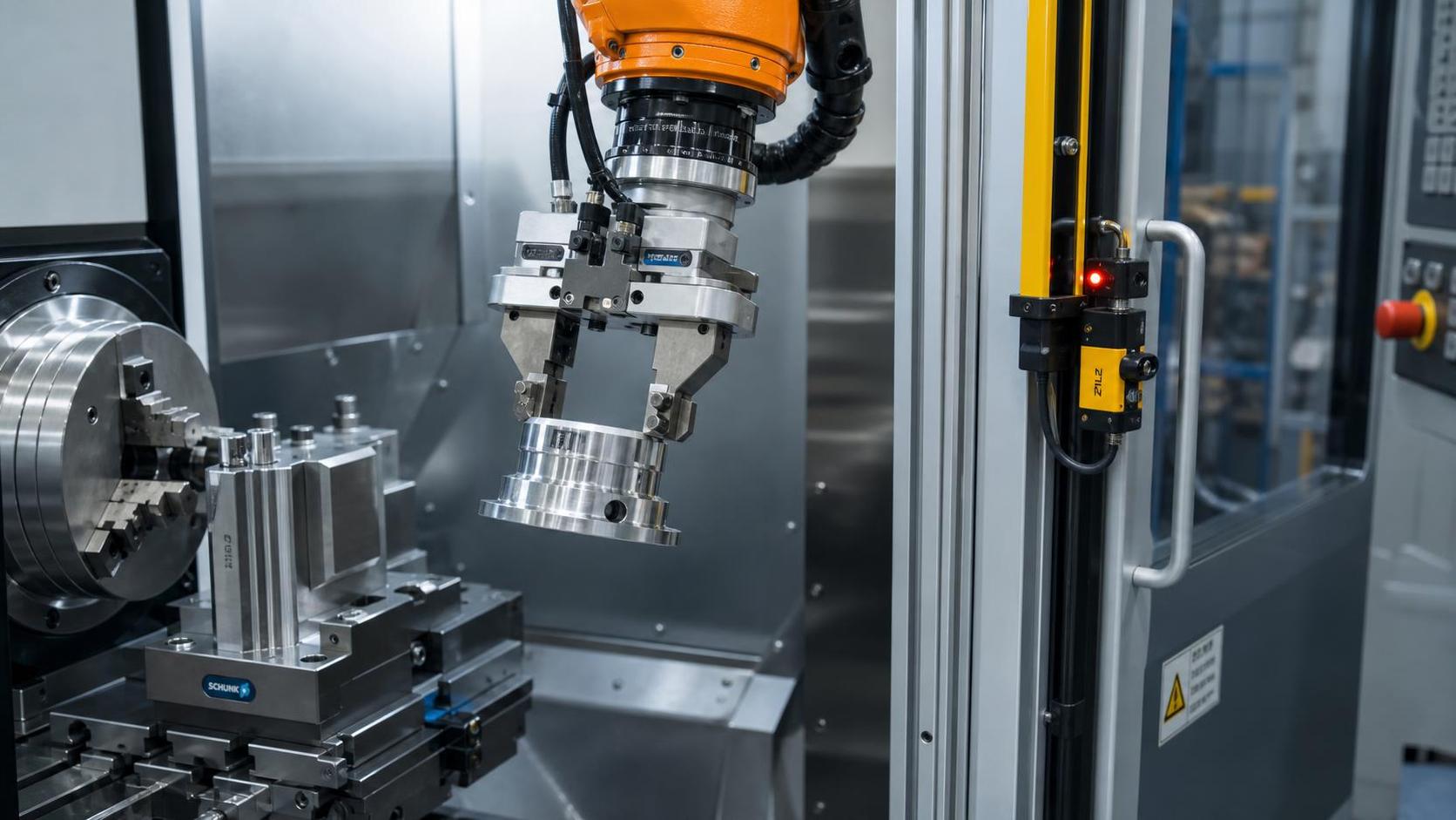
A delayed unloading cycle is often blamed on the machine unloading robot arm because it is the most visible moving component. In many cases, however, the robot is waiting for a machine-ready condition, a gripper confirmation, a safety release, or a stable part location that arrives late or intermittently. Changing robot speed or retouching points may hide the symptom for a short time, but it rarely removes the cause.
For after-sales maintenance personnel, the first task is to separate motion time from waiting time. A robot that spends 12 seconds moving and 25 seconds waiting is an integration problem. A robot that moves slowly because it is taking a long detour, avoiding a poorly defined fixture, or approaching an unstable workpiece is a process-design problem. Both can appear as “robot delay,” but they require different corrective actions.
Start With a Cycle Timeline, Not an Alarm List
Before changing parameters, capture the actual sequence from the final machining or drilling operation through part release, pickup, exit, and machine restart. Use robot controller timestamps, PLC event logs, CNC status history, or a simple observation sheet if no synchronized logging is available. The goal is to identify where the time is lost and whether it is repeatable.
A useful timeline normally includes:
- Machine cycle complete or machining finished signal
- Spindle stopped, axes in safe position, and chuck or clamp release status
- Robot request to enter the machine area
- Safety-zone release and door or guarding status
- Robot arrival at pickup point
- Gripper close command and part-present confirmation
- Machine confirmation that the part has cleared the fixture
- Robot exit from the protected zone
- Machine-ready signal for the next blank or next cycle
Measure both the average delay and the variation. A fixed 5-second delay after every cycle may be an intentionally configured dwell, a PLC timer, or a conservative safety sequence. A delay that changes from one cycle to another is more likely caused by unstable sensing, variable workpiece position, communication retries, chip buildup, air-pressure recovery, or intermittent safety conditions.
Do not rely only on the robot program’s displayed cycle time. That value often excludes time spent waiting on external inputs. A maintenance team needs the full cell cycle, including CNC, conveyor, fixture, safety PLC, robot, and downstream transfer equipment. The slowest dependency sets the practical output.
Check Whether the Handshake Is Complete and Properly Ordered
Many unloading delays come from a handshake that is technically functional but poorly sequenced. The robot may receive “cycle complete” before the spindle has fully stopped, before clamps have opened, or before the machine has moved to its unload position. The robot then waits at a safe approach point. Operators see the robot standing still and assume it is slow, although it is correctly obeying the machine’s interlock.
Review every signal exchanged between the CNC or machine PLC and the robot controller. At minimum, distinguish between “process complete,” “machine safe for robot entry,” “fixture open,” “part available,” “robot in machine,” “part removed,” and “machine clear.” Combining several physical states into one generic ready bit makes troubleshooting difficult and can create unnecessary waiting.
The signal order should also be examined. For example, the machine can often begin retracting tools and moving to a safe unload position before the final program-end confirmation is sent to the robot. Similarly, the robot may be able to travel toward a pre-entry position while the machine completes its final safe-axis motion. This overlap is useful only when the risk assessment and safeguarding logic permit it. Removing a delay by bypassing an interlock is not a production improvement; it transfers risk to the next incident.
Look closely at edge-triggered versus level-triggered signals. A brief pulse can be missed when a robot is busy, in fault recovery, or using a slower scan cycle. A maintained request with a clear acknowledgement is usually easier to diagnose. Where the robot and machine use different fieldbus networks or interface gateways, verify signal refresh time, fault behavior after communication loss, and restart behavior after a controller reset.
Common handshake faults that look like robot faults
- The CNC sends a program-end bit, but the robot is waiting for a separate spindle-safe signal that never changes due to an address mapping error.
- The machine opens its clamps only after receiving robot-arrived confirmation, while the robot waits for clamp-open confirmation before entering.
- A part-removed signal is issued by robot motion completion rather than by the gripper’s actual part-present sensor.
- A PLC timer remains active after a manual recovery, adding an unexplained dwell to subsequent automatic cycles.
- The robot acknowledges a request before it has reached the required safe position, allowing the machine sequence to advance too early and forcing later waits.
When signals are unclear, build a temporary I/O monitor table with the expected state at each step. It is less elegant than relying on a program narrative, but it exposes mismatched assumptions between the machine builder, robot integrator, and maintenance team.
Gripper Confirmation Is Often the Weakest Link
The gripper has to prove three different conditions: it reached the pickup position, it has a secure hold on the workpiece, and the workpiece has cleared the machine fixture. A single “gripper closed” input proves none of these reliably. The fingers may close on a shifted component, chips, a burr, or empty space.
Delayed unloading after several good cycles commonly points to sensing or mechanical variation at the gripper. Check whether part-present sensing is appropriate for the material and surface condition. Inductive sensors may behave differently with coated steel, thin sections, or a changing air gap. Vacuum pressure switches can be affected by porous surfaces, scale, oil, and contaminated cups. Mechanical switches may be reliable on a stable part family but become unsuitable when part thickness varies.
Also inspect the mechanical condition of the end effector. Loose fingers, worn locating pads, bent brackets, damaged pneumatic tubing, and low air pressure can add small but cumulative delays. A gripper that requires repeated close attempts may never generate a formal robot alarm if the program simply waits for confirmation until a timeout is reached.
For heavy, long, or flexible parts, pickup confirmation should be assessed under motion, not only at the pickup point. A part can be detected while resting in the fixture and then slip or rotate as the robot accelerates. Excessive acceleration limits may be a necessary protection, but they should not be used to compensate for a gripper with inadequate contact area or poor center-of-gravity control.
Fixture Positioning Can Turn a Fast Robot Into a Slow One
A machine unloading robot arm depends on repeatable presentation of the finished part. If the part shifts in the chuck, nest, clamp, or support rollers, the robot will need a wider approach path, slower final motion, additional vision checks, or recovery moves. All of these reduce output, even when robot axes and drives are working correctly.
Inspect fixture condition with the same discipline used for robot mastering. Check stop positions, clamp stroke, locator wear, chip accumulation, hydraulic pressure stability, and workpiece support. Pay particular attention to processes that create burrs, swarf, coolant residue, or thermal distortion. These conditions can prevent the component from fully seating after machining and change the pickup height by only a few millimeters, enough to trigger cautious motion or gripper failures.
In beam processing, the issue is often more pronounced because material geometry varies over a long workpiece. A system handling H-beams, channels, or box sections needs consistent reference surfaces and support during pickup. Where drilling is performed on several faces, such as on an H beam 3D drilling machine, the unloading logic should account for part length, flange and web dimensions, remaining chips around drilled holes, and the material’s expected exit orientation. A robot path proven on one beam size may introduce clearance losses or pickup uncertainty on another.
Do not solve repeated positional variation by continuously widening robot tolerances. Wider tolerances can let the cell run temporarily, but they may allow marginal pickups, tool collisions, fixture contact, or inconsistent placement downstream. Establish whether the variation belongs to the incoming material, machine clamping, fixture hardware, or robot reference frame before modifying the robot program.
Safety Interlocks Must Be Timed as Well as Verified
Safety circuits are frequently involved in unload delays, especially in cells with automatic doors, light curtains, area scanners, safety mats, or shared robot zones. The maintenance question is not whether the safety system exists, but whether its sequence causes unnecessary idle time without improving the intended protection.
Observe the time between machine-ready status and permission for the robot to cross into the machine envelope. If the delay is consistent, check door-open and door-closed confirmation timers, safety PLC filtering, scanner zone switching, and robot safe-speed transitions. Some cells deliberately add time after a door command to ensure mechanical movement is complete. That may be justified, but a timer should reflect actual door travel and sensor response rather than an inherited commissioning value.
Shared zones deserve special attention. A robot may be waiting for a conveyor, pallet station, loading robot, or machine axis to release a virtual or physical zone. If the cell uses safety-rated position monitoring, verify that the relevant device returns to its defined safe position at the end of every cycle. Small deviations can leave the zone occupied even though no obvious collision risk is visible to an operator.
Never bridge safety contacts or force a safety condition solely to prove a timing theory in production. Use approved diagnostic procedures, controlled test conditions, and the cell’s documented safety architecture. A well-run investigation compares normal timing against the designed sequence without disabling the protection that governs the sequence.
Separate Robot Motion Limits From Process Limits
Once waiting time has been isolated, evaluate robot motion itself. Confirm that payload, center of gravity, tool mass, cable dress package, and inertia values match the installed end effector and workpiece. Incorrect payload data can cause the controller to limit acceleration, generate path smoothing changes, or apply protective motion behavior. It can also reduce repeatability over time because braking and joint loads are not being managed as intended.
Review the path through the cell rather than only the maximum programmed speed. A robot can lose more time at multiple low-speed approach points than on a long transfer. Check whether approach distances are larger than necessary, whether excessive fine-position stops are used, and whether the robot is waiting at locations that could be converted into blended motion. Any path change must preserve clearance from fixtures, machine doors, clamps, spindles, and material handling equipment.
There is a practical distinction between reducing robot cycle time and increasing cell throughput. If machining takes longer than unloading, a faster robot may not raise output. If the machine finishes while the robot is still placing the previous part, motion optimization may be valuable. The timeline makes this distinction visible and prevents maintenance work from focusing on a non-bottleneck.
A Practical Recovery Sequence After Delays Appear
When delays begin after stable operation, avoid making several changes at once. First determine whether the change is tied to a particular material size, production program, tool condition, shift pattern, machine mode, or recovery event. Then inspect the signal state at the point where the robot stops. This approach preserves evidence that can be lost when programs are immediately edited or controllers are repeatedly reset.
- Record the exact step where the cell waits and the state of relevant CNC, PLC, robot, safety, and gripper signals.
- Compare one normal cycle and one delayed cycle using the same part type where possible.
- Inspect the part and fixture for chips, burrs, movement, clamp marks, or incomplete release.
- Check gripper mechanics and sensing before altering robot points or speed settings.
- Verify that the safety sequence reaches every required state in the expected order.
- Only after external conditions are stable, review robot payload data, path points, acceleration settings, and controller alarms.
The most useful corrective action is the one that makes the sequence observable and repeatable. A machine unloading robot arm should not need an operator to judge whether a part is free, whether a clamp is fully open, or whether a zone is clear. When those conditions are accurately sensed and communicated, the robot can move at a speed that is both efficient and defensible from a safety and maintenance standpoint.
search
Recommended Products
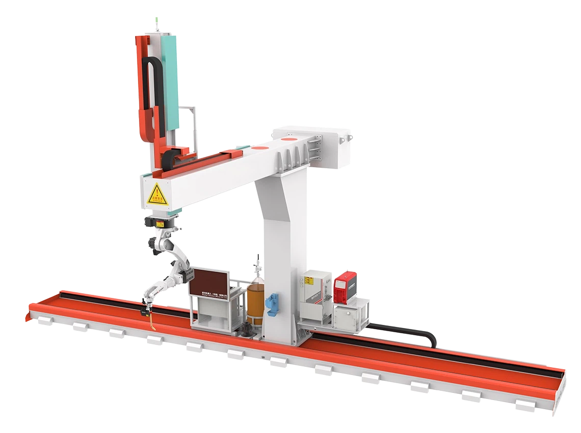
 9 axis cantilever type welding robot9 axis cantilever type welding robot for large steel workpieces with auto tracking, 3D import, and efficient CNC welding automation.
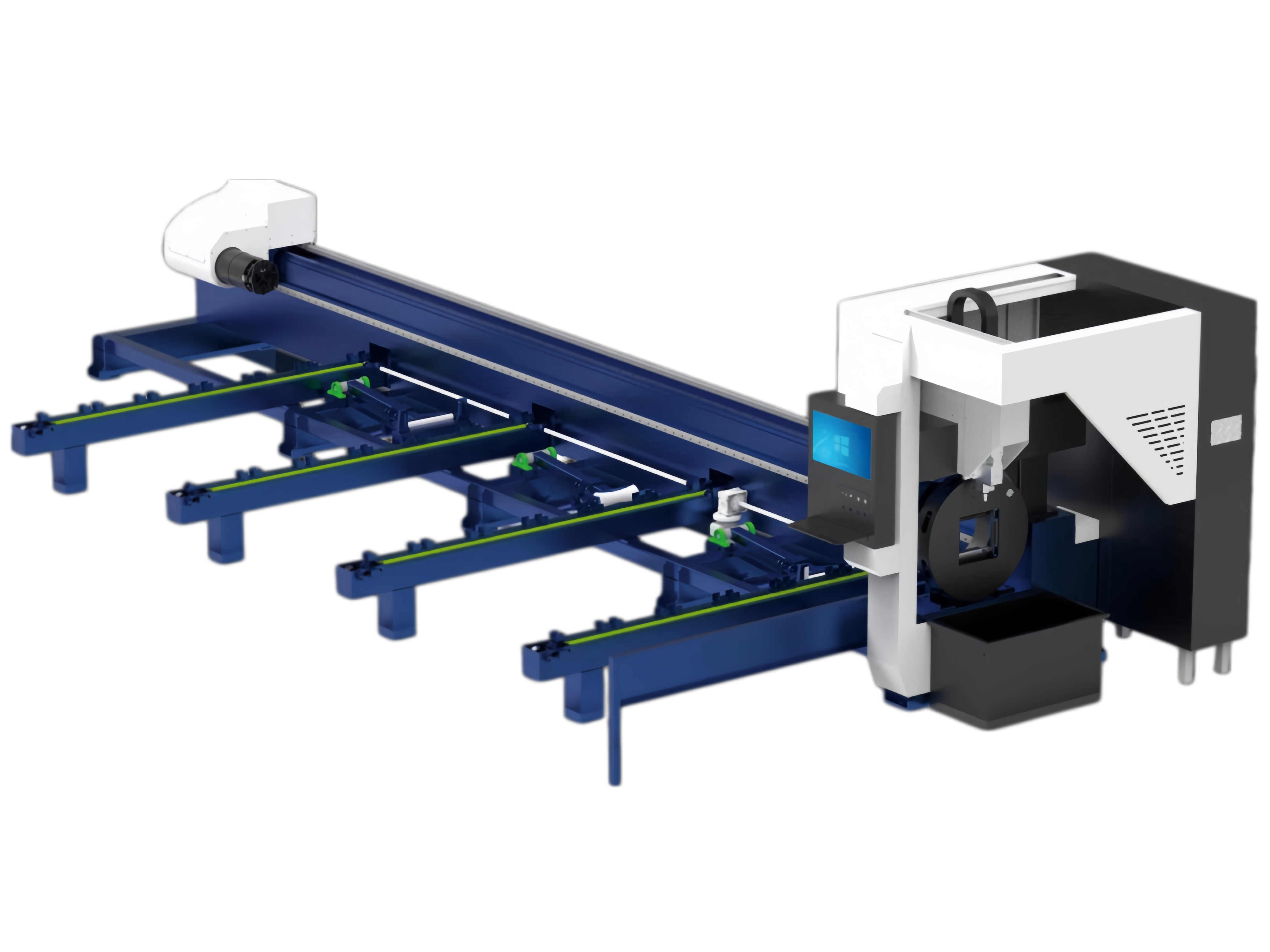
 Pipe cnc fiber laser cutting machine1.Introduction for Pipe cnc fiber laser cutting machine:
The laser cutting machine focuses the laser beam emitted from the laser source through the optical path system into a high-power-density laser beam. This laser beam is directed onto the surface of the workpiece, causing it to reach the melting point or boiling point. At the same time, the high-pressure gas coaxial with the laser beam blows away the molten or vaporized metal. Beveling & Milling Edge For Heavy TankThis series of heavy tank beveling and milling edge machines is a specialized, high-efficiency solution designed for beveling large storage tanks, pressure vessels, and heavy structural components. The main frame features an integrated welded construction followed by high-temperature stress-relief annealing, effectively eliminating internal stresses to ensure long-term dimensional stability and prevent deformation. The machine combines high-rigidity design with advanced control technology, purpose-built to handle the challenges of extra-thick plates and oversized workpieces.
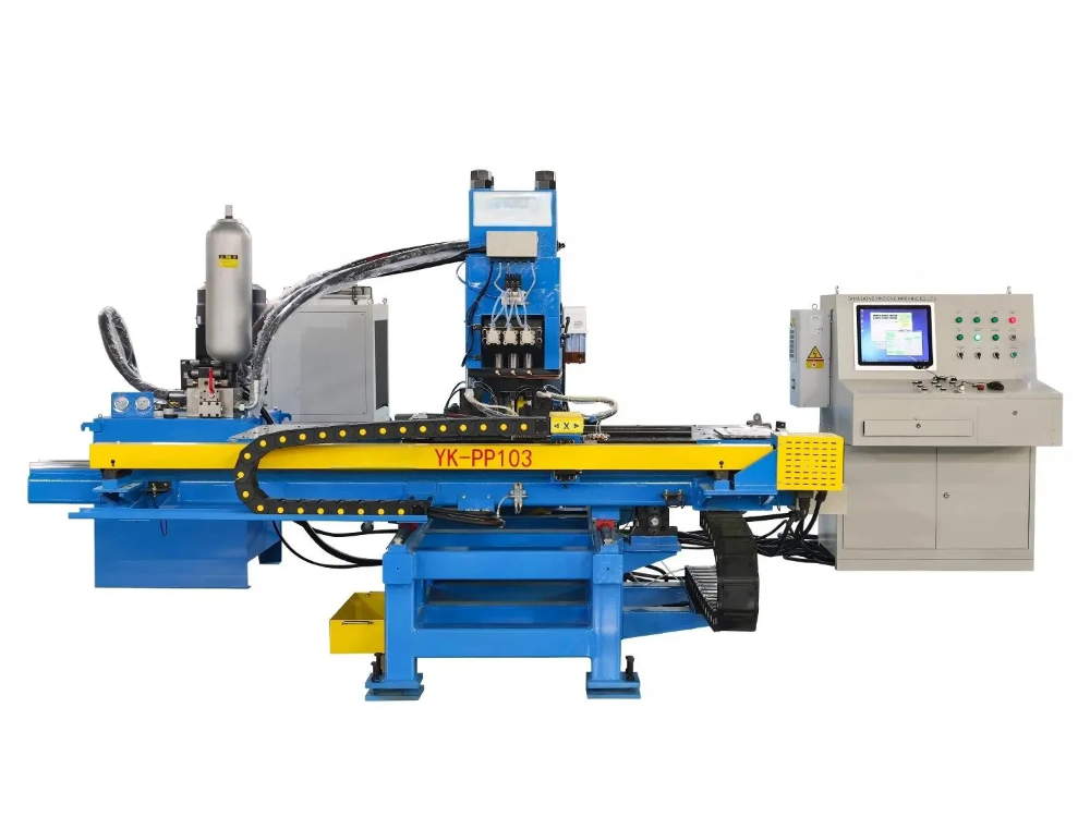
- CNC Punching And Marking Machine For Steel PlatesModels: YK-PP103 / YK-PPR103 / YK-PP104 / YK-PPR104
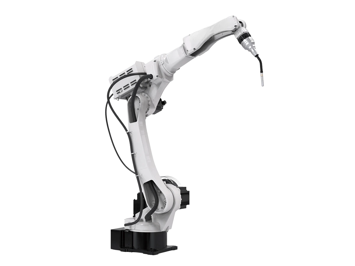
This series is a specialized CNC punching and marking machine designed primarily for steel plate processing in the steel tower industry. It is also well-suited for punching and marking applications across various other industrial sectors. - 6 Axis 2000mm ArmSpan MlG Industrial Welding RobotThis welding robot is designed for reliable arc welding in harsh production environments, featuring a long reach, stable repeatability, and flexible installation.
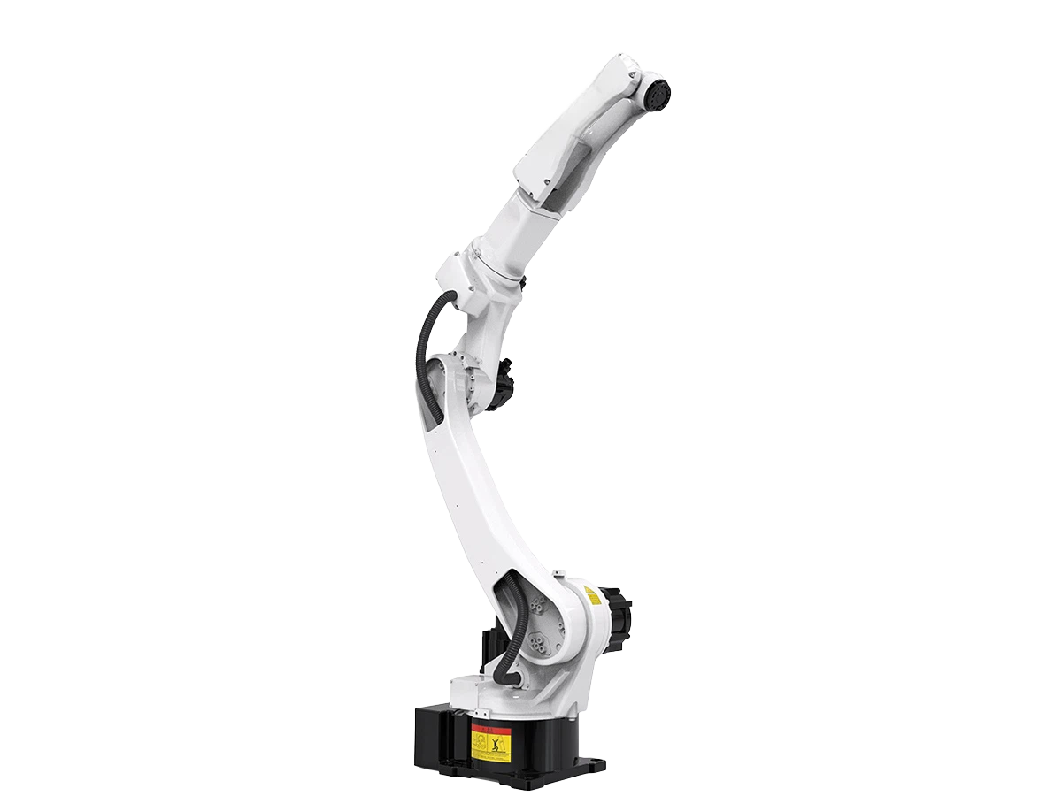
- Multipurpose Handing Robot BR20iB-20Explore the BR20iB-20 multipurpose robot for handling, welding, and cutting with 6-axis motion, ±0.08 mm repeatability, and flexible installation.

Send Us A Message