




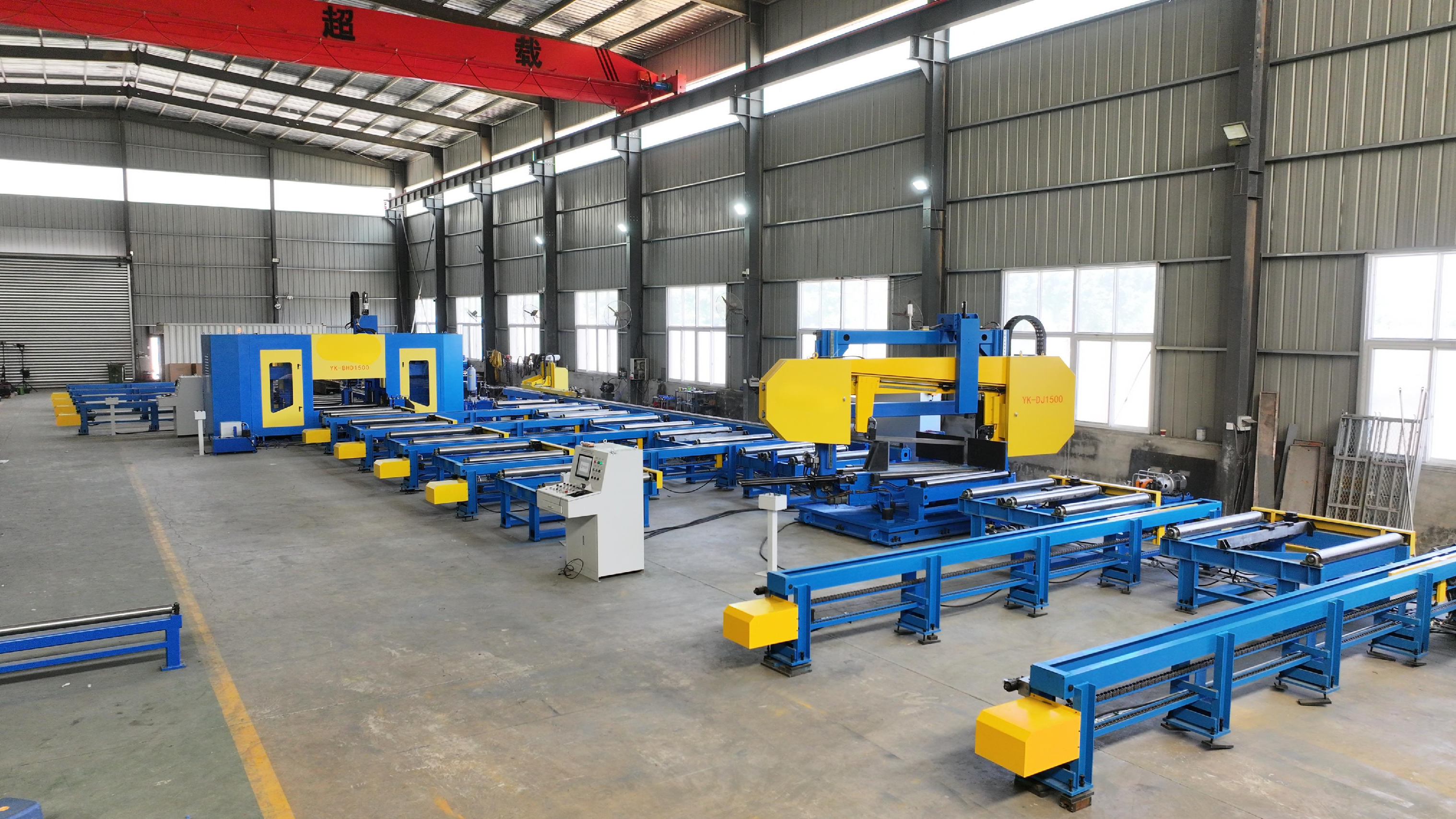
H beam 3D drilling machine
The 7‑axis CNC steel three‑dimensional drilling machine utilizes seven servo motors to achieve drilling positioning in two vertical directions, one horizontal direction, and one longitudinal direction, as well as servo feed for three main spindles. On each of the three drilling surfaces, there is one drilling spindle, each driven by a variable‑frequency motor. The drilling spindles are servo‑driven for precise feed control.
Full-range Machinery & Customized Non-standard Solutions
Authorized Certificates & Independent R&D Patents
Over 10 Years Global Export & Worldwide Project Cases
Navigation

H beam 3D drilling machine Description
1.Introduction for H beam 3D drilling machine:
This machine tool is primarily designed for drilling operations on H‑beams, channel steel, and box‑type beams, and is widely used in industries such as steel structure construction, bridge building, and parking garage fabrication.
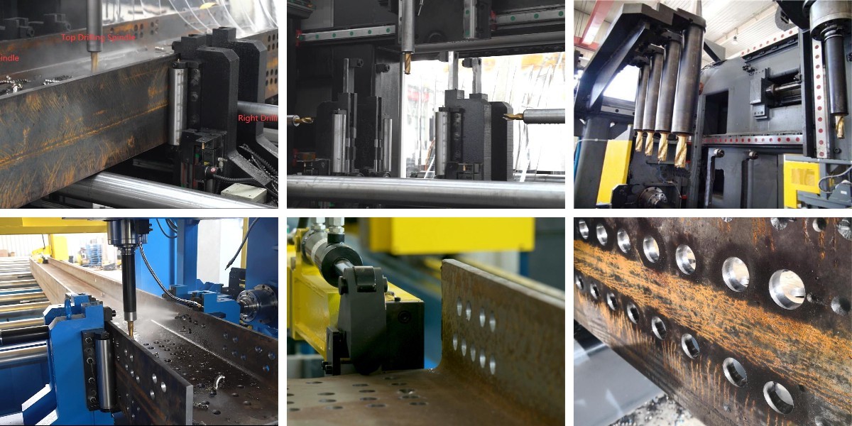
The 7‑axis CNC steel three‑dimensional drilling machine utilizes seven servo motors to achieve drilling positioning in two vertical directions, one horizontal direction, and one longitudinal direction, as well as servo feed for three main spindles. On each of the three drilling surfaces, there is one drilling spindle, each driven by a variable‑frequency motor. The drilling spindles are servo‑driven for precise feed control.
When the hole diameters on all three surfaces are identical, the workpiece can be fully processed in a single pass through the equipment, delivering high efficiency and exceptional hole positional accuracy. This machine is therefore an indispensable asset for quality assurance in the steel structure manufacturing industry.
2.Technical parameter for H beam 3D drilling machine
3.Characters for H beam 3D drilling machine:
3.1 Overall Design and System Composition
The machine features an optimized integrated design with a high‑quality machine body and drilling units, ensuring excellent stability and rigidity during high‑speed drilling operations. The system mainly comprises the main machine, three CNC sliding tables, three drilling spindle boxes, a clamping device, a detection device, a cooling system, a scrap box, a hydraulic station, a lubrication system, and optional tool magazine and marking unit.
3.2 Main Machine Structure
The main machine is fabricated by welding square steel tubes, with structural reinforcement applied at high‑stress areas. Post‑weld artificial aging treatment is carried out to ensure the stability of the main machine, thereby guaranteeing the overall accuracy of the equipment.
3.3 CNC Sliding Tables
Three CNC sliding tables are provided: fixed‑side, movable‑side, and intermediate. These three tables are similar in construction, each consisting of a sliding plate, a slide base, and a servo drive system.
3.4 CNC Axis Configuration
The three sliding tables incorporate a total of six CNC axes, comprising three feed axes and three positioning axes. Each CNC axis is guided by precision linear rolling guides and driven by an AC servo motor with a ball screw mechanism, ensuring high positioning accuracy.
3.5 Drilling Spindle Boxes
Three spindle boxes are mounted on the three CNC sliding tables for horizontal and vertical drilling operations. Each drilling spindle box can operate independently or simultaneously with the others.
3.6 Spindle and Drive System
The machine is equipped with high‑speed precision spindles from a renowned Taiwanese brand, featuring a BT taper design that accommodates both carbide and high‑speed steel drills. All CNC axes are guided by heavy‑duty roller linear guides and driven by servo motors with roller screws, ensuring high rigidity and positional accuracy.
4.More details for H beam 3D drilling machine
products faq
An H Beam Production Line is a complete automated system for manufacturing H-shaped steel beams. It typically includes an uncoiler, leveling unit, assembly machine, tack welding machine, main submerged arc welding (SAW) system, straightening machine, cutting equipment, and material handling conveyors. All components work together to transform steel plates or coils into finished H-beams with high efficiency and consistent quality.
Submerged Arc Welding (SAW) is the most commonly used process for main welding in H beam production lines. It offers deep penetration, high deposition rates, excellent weld quality, and minimal spatter—making it ideal for heavy structural beams. Some lines also incorporate gas-shielded welding for tacking or light sections.
The line is adjustable to accommodate a wide range of beam sizes. Standard configurations typically handle web heights from 200mm to 1,500mm, flange widths from 100mm to 800mm, and material thicknesses from 6mm to 60mm. Custom sizes can be accommodated with tailored equipment design.
After welding, the thermal distortion caused by heat input is corrected by a straightening machine, which applies pressure to bend the beam back to the required straightness tolerance. In addition, precision assembly fixtures and automated control systems ensure accurate web-flange positioning before welding, maintaining consistent product dimensions throughout production.
Routine maintenance includes checking and replacing welding consumables (flux, wire, contact tips); inspecting conveyor chains, rollers, and bearings; monitoring hydraulic system oil levels and seals; cleaning the flux recovery system; and verifying the straightening machine's adjustment accuracy. We provide comprehensive maintenance schedules, spare parts support, and on-site technical assistance to minimize downtime.