




Material Handling Robot Arms: Which Specs Matter for Heavy-Duty Fabrication?
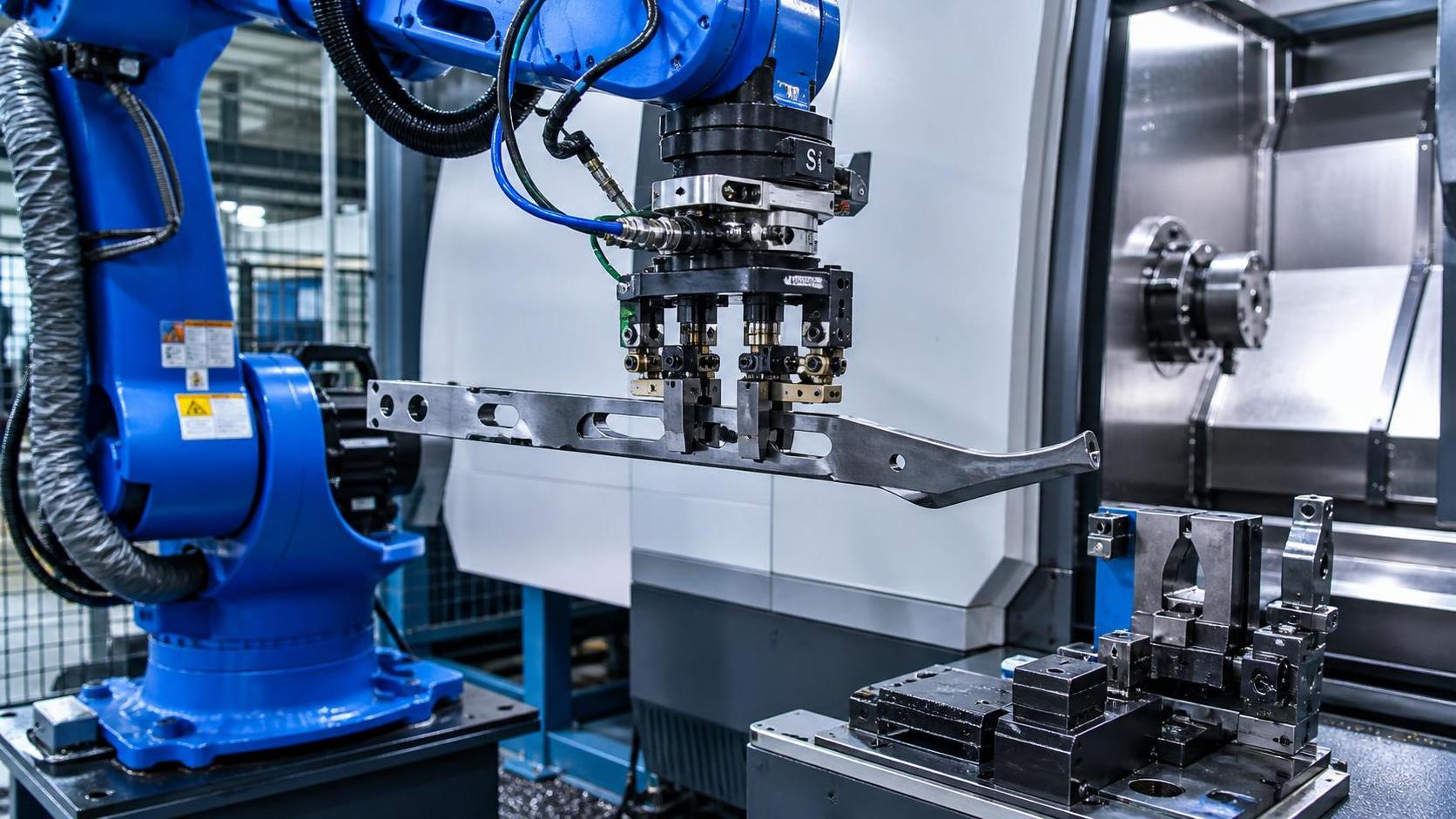
Heavy-duty capability is defined by the moving load, not the nameplate payload alone
A material handling robot arm for fabrication should not be selected by comparing nominal payload figures alone. In heavy-duty cells, the robot carries more than a workpiece: the true moving mass includes the gripper or fixture, adapter plates, pneumatic or hydraulic components, sensors, cable dress packs, and sometimes a part-positioning device. A robot rated for a 200 kg payload may be poorly matched to a 160 kg steel component if the end effector adds 55 kg and shifts the load center far from the flange.
The practical selection question is whether the robot can control the complete load at the required reach, orientation, acceleration, and duty cycle without reaching axis torque limits. Payload, center of gravity, and moment of inertia must therefore be evaluated as one set of values. A supplier should be able to review the proposed end-of-arm tooling and provide a load calculation rather than simply confirming that the workpiece weight is below the published payload rating.
This distinction becomes critical with fabricated steel parts that are long, asymmetric, or variable in geometry. A short, dense forging may be easy to move at a given weight. A long plate, frame member, cylindrical shell, or welded assembly of the same weight can create far higher rotational loading because its center of gravity sits farther from the robot wrist.
Payload must include gripper mass, process variation, and a realistic reserve
Procurement specifications should state the maximum handled mass as a complete handling package. A useful request to an integrator or robot supplier includes:
- Maximum and minimum workpiece weight;
- Workpiece dimensions, including the longest projected length;
- Estimated center of gravity and permissible variation;
- Mass and dimensions of the gripper, fixture, tool changer, and cabling;
- Whether the part contains scale, oil, weld spatter, sharp edges, or surface irregularities;
- Required part orientation during loading, unloading, transfer, and presentation.
It is risky to size a robot with no margin simply because a static calculation fits the catalog value. The available capacity changes with arm posture, acceleration, and the load’s inertia. The application may also evolve: a revised part family can add reinforcing ribs, longer flanges, or heavier handling fixtures. A modest capacity reserve can prevent an automation cell from becoming unusable when production requirements change.
That said, oversizing without examining the full cell has consequences. A larger robot can increase capital cost, floor loading, safety-envelope size, energy demand, and the size of protective fencing. It may also be less suitable for short, rapid motions if the application is actually constrained by lightweight parts and high cycle rates. The correct choice is not the largest material handling robot arm available; it is the one whose load envelope remains acceptable across all approved parts and operating positions.
Reach is a three-dimensional envelope, not a single radius
Maximum reach is often treated as a simple distance from the robot base to the farthest point. That figure is insufficient for fabrication cells. The arm must reach into a CNC machine, clear a door opening, avoid fixtures and conveyors, rotate the part, and place it accurately without entering singular or mechanically restricted positions.
A robot may technically reach a machine chuck or a welding fixture while still being unable to approach at the angle required for safe loading. Wrist orientation, elbow clearance, and the gripper’s physical dimensions can eliminate positions that appear available in a two-dimensional layout. Internal machine structures matter as well: coolant guards, vises, tailstocks, pallets, clamping towers, and part supports can obstruct the robot’s path.
For machine tending, the usable work envelope should be checked against the full loading sequence: pick point, approach point, machine-entry point, placement point, clamp-clearance position, extraction position, and discharge location. For press brakes, cutting systems, and plate-processing equipment, the robot must also clear material movement zones and operator access areas.
Base mounting height deserves the same attention. A robot mounted on the floor may have enough horizontal reach but insufficient vertical access into a machine. A pedestal can improve access but may create overhead interference or require a stronger foundation. Ceiling or wall mounting can release floor space, but it changes cable routing, service access, and structural requirements.
Cycle time depends on acceleration limits and process coordination
Robot speed specifications can mislead when evaluated outside the application. Published maximum joint speeds do not represent the achievable cycle time for a heavy, off-center steel load. Acceleration and deceleration are usually reduced as inertia rises, and the robot must slow further near equipment, safety zones, or precise insertion points.
For a CNC loading cell, the relevant cycle is not merely “pick-and-place time.” It includes machine door operation, chuck or vise confirmation, part-present signals, clamp release, spindle stop conditions, blow-off or coolant drain time, and the time required to keep the next blank ready. If machining takes several minutes, an extremely fast robot offers little benefit. If the machine cycle is short, robot motion, gripper actuation, and interface delays can become the limiting factor.
In welding-related fabrication, handling may be tied to fixture rotation, tack-weld confirmation, seam access, cooling time, and part transfer. A robot should not be judged as a stand-alone moving device when the actual production constraint sits at a fixture, machine, or inspection point.
A credible proposal should show a simulated or calculated cycle based on the actual part geometry and cell sequence. The cycle-time assumption should identify whether it includes gripper actuation, machine handshakes, safety-zone transitions, and realistic acceleration settings. A claimed cycle based only on empty-arm movement is not a production-rate commitment.
Repeatability is important, but absolute accuracy may be the real issue
Robot repeatability indicates how consistently the arm can return to a taught point. It is highly relevant for repetitive loading, unloading, fixture presentation, and pallet transfer. It does not automatically mean the robot can locate a randomly positioned part with the same level of absolute accuracy.
Fabrication environments frequently introduce variation: incoming plates can shift on a pallet, castings may vary between batches, welded structures can distort, and handling racks may not locate parts precisely. Where the robot must find a part rather than return to a fixed fixture position, the system may need vision guidance, probing, compliant tooling, floating grippers, or mechanically robust locating stations.
For machine tending, the machine fixture should normally establish the final position of the workpiece. The robot’s function is to place the part consistently enough for clamps, locators, or a chuck to capture it. Trying to compensate for poor fixture design through tighter robot specifications often adds cost without solving the root problem.
Repeatability also needs to be considered across the actual operating conditions. Thermal changes, high payloads, long reaches, mechanical backlash in peripheral equipment, and fixture wear can affect cell results even when the robot itself meets its published specification.
End-of-arm tooling is often the decisive component
In heavy fabrication, the gripper is not a minor accessory. It determines whether the robot can reliably hold parts with mill scale, oil residue, sharp edges, holes, curved surfaces, or inconsistent dimensions. A handling concept that looks feasible with a clean sample part may fail when production material has surface contamination or variation.
Common gripping approaches include mechanical clamps, magnetic grippers, vacuum systems, forks, hooks, and dedicated fixtures. Each has limitations. Magnetic gripping depends on ferrous material, sufficient contact area, surface condition, and safe release control. Vacuum systems can be unsuitable for rough, porous, hot, or heavily scaled surfaces. Mechanical clamps can offer positive retention but may require consistent geometry and can interfere with machine access. Fork-style handling may be effective for stable parts but usually requires controlled rack presentation.
The gripper should include appropriate part-presence confirmation. Depending on the handling method, this may involve pressure monitoring, jaw-position sensing, magnetic confirmation, load monitoring, or external sensors. A signal that the gripper has actuated is not necessarily proof that the part is securely held.
Tooling weight must be kept under control, but reducing mass should not compromise stiffness. A flexible gripper can allow a heavy part to swing during acceleration, increasing settling time and reducing placement reliability. The best design balances mass, rigidity, gripping security, maintenance access, and the ability to accommodate part variation.
Environmental resistance and duty cycle should match fabrication conditions
Fabrication plants expose robots to conditions that are harsher than those in clean assembly operations. Welding spatter, abrasive dust, grinding particles, cutting fluid mist, heat, metal chips, and scale can affect cable systems, joints, sensors, and grippers. The robot’s protection rating, dress package, wrist design, and cable routing should be matched to the actual exposure rather than the general description of the facility.
Where the robot works near welding operations, buyers should establish whether it will be exposed to direct spatter, radiant heat, welding fumes, or electromagnetic interference. Protective covers may help, but they can restrict motion or retain heat if poorly designed. In laser or plasma cutting applications, the handling arrangement must also respect the machine’s guarded process area and any manufacturer-specific access conditions.
Duty cycle deserves similar scrutiny. A system running a few transfers per hour has different thermal and wear demands from one operating continuously across multiple shifts. Ask for maintenance intervals for joints, reducers, cables, grippers, lubrication points, and safety devices. Availability depends on more than robot reliability; a difficult-to-service gripper or inaccessible cable path can create disproportionate downtime.
Heavy plate operations require a cell-level view
When handling plate for rolling, bending, or forming, the robot and the forming machine must be assessed together. A 50 mm steel plate is not simply a heavier version of thin sheet: plate deflection, edge condition, center-of-gravity uncertainty, and the need for controlled presentation can change the handling method completely.
For example, a Mechanized bending machine with 3 roller designed for large plate work may process material at thicknesses of 50 mm or more. In that setting, the automation requirement may involve feeding, supporting, repositioning, or removing partially formed cylindrical or conical workpieces. The handling system must account for changing geometry during rolling, not just the blank plate weight. A part that becomes curved can require a different grip location, larger clearance zone, and more careful collision analysis than the initial flat sheet.
It may be more practical to combine robotic handling with powered infeed tables, side supports, lifting devices, transfer carts, or dedicated manipulators. A six-axis robot is valuable when the process requires orientation flexibility, but it is not automatically the most economical or safest answer for every high-mass plate movement. The equipment layout should identify which motions require robotic articulation and which are better performed by purpose-built material support equipment.
Integration specifications should be written before supplier comparison
Robot hardware can be comparable on paper while integration scope differs substantially. A complete quotation should make clear who supplies the gripper, guarding, safety controller, machine interface, electrical cabinet, programming, part racks, foundations, installation, commissioning, and operator training. Ambiguity in these interfaces is a common source of unexpected project cost and schedule delay.
Machine communication requirements should be defined early. At minimum, the cell needs reliable signals for machine-ready status, door status, clamp state, cycle start permission, fault conditions, emergency stops, and safe recovery. Older CNC machines may require interface upgrades before unattended tending is viable. The robot cannot compensate for a machine that lacks safe, repeatable automatic clamping or clear process-status signals.
Controls integration should also address data ownership, backups, remote support permissions, and the availability of electrical drawings and PLC documentation. A cell that can run only when a specialist programmer is available has a different operating risk from one with documented recovery procedures and maintainable programs.
Safety compliance is a design requirement, not a closing document
Industrial robot cells require a documented risk assessment and safeguarding concept appropriate to the installation jurisdiction. Relevant standards commonly considered include ISO 10218 for industrial robot safety and ISO 12100 for risk assessment and risk reduction. For collaborative applications, ISO/TS 15066 may be relevant, but heavy-duty fabrication handling should not be assumed suitable for collaborative operation merely because a robot model offers collaborative functions.
Large moving steel parts create hazards beyond the robot itself: dropped loads, pinch points, sharp edges, unstable racks, stored energy in clamps, and unexpected part movement during release. Safeguarding may require fencing, interlocked access points, safety scanners, light curtains, safe speed functions, and defined manual-recovery procedures. The design must also allow safe removal of a failed or damaged workpiece.
For cross-border projects, certification claims should be examined in relation to the full cell, not only the robot. A robot component may carry relevant declarations or markings, while the integrated system still requires its own conformity assessment, technical documentation, and site-specific validation.
What should be verified before placing an order
The strongest purchasing decision is supported by evidence tied to the intended application. Request a layout showing robot positions, machine access, safety boundaries, and service clearance. Require payload and inertia calculations for the complete end effector and the heaviest approved part. Review a cycle-time study that includes process handshakes rather than only robot motion.
Before shipment, acceptance criteria should address part types, placement repeatability, gripping confirmation, machine interface behavior, safety functions, recovery after faults, documentation, and spare-parts recommendations. A factory acceptance test can validate the agreed sequence where representative tooling and workpieces are available. Site acceptance should confirm that real foundations, utilities, machine interfaces, material condition, and production constraints do not alter the outcome.
The specification that matters most is the one that proves stable operation under the heaviest, longest, least forgiving workpiece the cell is expected to handle. When payload calculations, reach studies, gripper design, machine interfaces, and safety requirements are treated as connected decisions, the selected robot arm becomes a reliable production asset rather than an expensive component waiting for a workable cell design.
search
Products Navigation
Send Us A Message