




Ready Welders and Welding Equipment: What ‘Plug-and-Play’ Really Means — Voltage Stability, Duty Cycle, and Input Power Requirements Explained
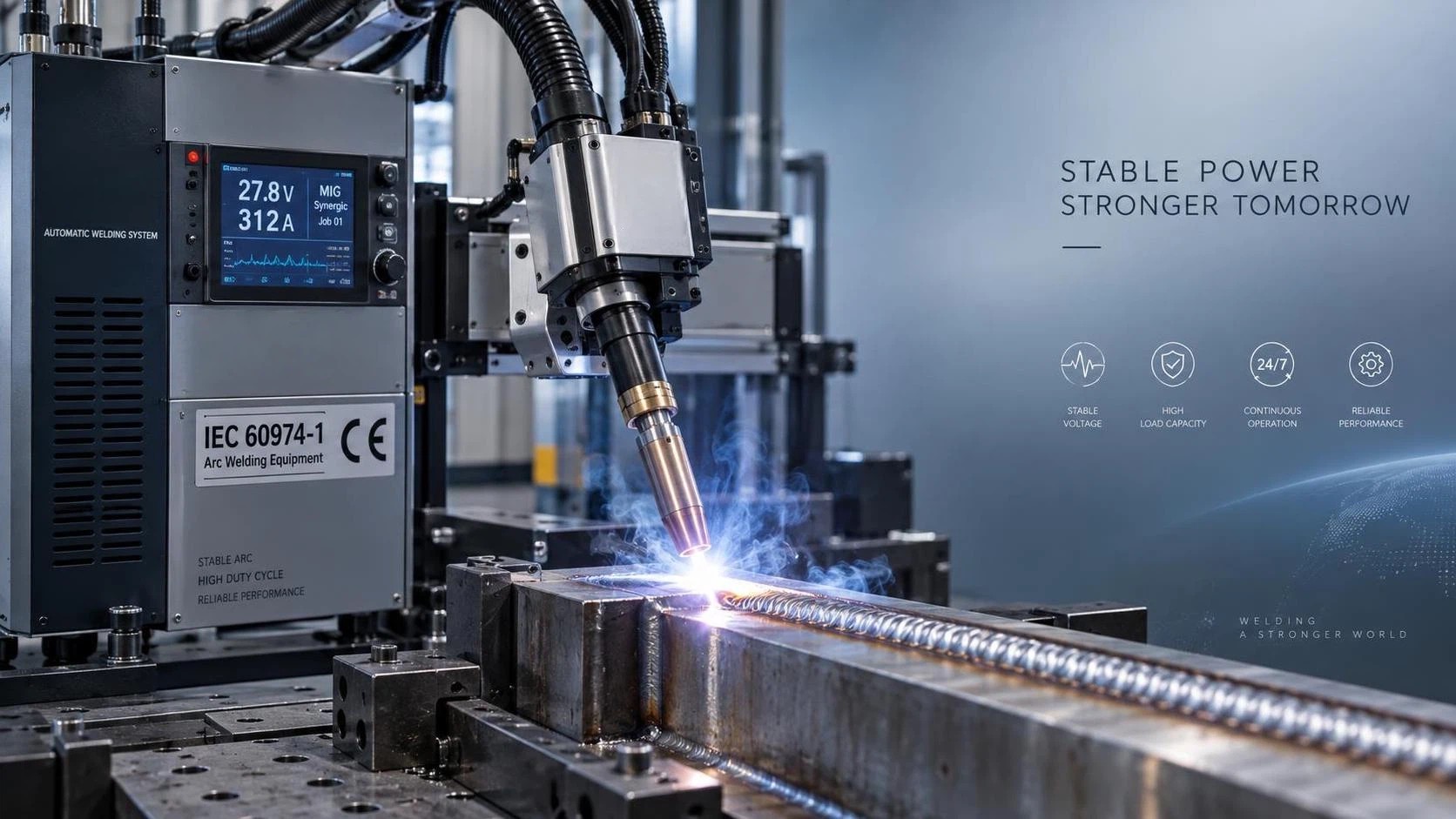
“Plug-and-play” Ready Welders and Welding Equipment sounds ideal—especially when you’re under pressure to deploy new welding capacity fast. But in real manufacturing environments, that label often masks three critical technical realities: voltage stability under dynamic load, duty cycle performance that matches your production rhythm, and input power requirements that align with your facility’s electrical infrastructure—not just the nameplate rating on the spec sheet.
For procurement professionals sourcing industrial-grade solutions—particularly automatic welders, robotic cells, or CNC-integrated systems—these aren’t theoretical concerns. They’re the difference between a system that delivers consistent arc starts and stable metal transfer across shifts… and one that trips breakers during multi-pass runs, overheats at 60% utilization, or forces costly site upgrades because its “230V single-phase” claim ignores actual inrush current and harmonic distortion.
Voltage Stability Isn’t Just About Nominal Input
Many Ready Welders and Welding Equipment units list “230V ±10%” as acceptable input. That looks reassuring—until you measure actual line voltage *at the machine terminals* during peak welding cycles. Voltage sag of 15–20 V is common in older plants or shared circuits feeding multiple high-current devices (e.g., hydraulic presses, plasma cutters, or induction heaters). A poorly regulated inverter-based welder may respond with arc instability, porosity, or even shutdown—even if the nominal supply stays within spec.
What matters isn’t just whether voltage stays within ±10% *on paper*, but how tightly the internal power stage regulates output despite fluctuating input. Look for machines with active PFC (Power Factor Correction) and wide-input-range inverters—especially if your facility has long feeders, aging transformers, or variable loads. Units certified to IEC 60974-1 (arc welding equipment safety) must withstand specified voltage dips—but that doesn’t guarantee stable arc performance. Real-world validation requires testing under representative load profiles, not just static compliance checks.
Duty Cycle: The Most Misunderstood Spec
Duty cycle is routinely misread as “how long it can run before overheating.” In practice, it’s a thermal rating based on a *specific test condition*: typically 10-minute cycles at rated output, with ambient temperature held at 40°C. A “60% duty cycle at 300A” means the unit can sustain 300A for 6 minutes out of every 10—*if* cooling is unimpeded, airflow unrestricted, and ambient stays at 40°C.
In actual fabrication lines, conditions rarely match the lab. Dust accumulation on heatsinks, restricted ventilation in enclosed cells, or ambient temperatures exceeding 40°C (common near furnaces or in tropical climates) can slash effective duty cycle by 30–50%. Worse, many procurement teams assume robotic welding cells operate at lower average amperage—so duty cycle becomes irrelevant. Not true. Robotic MIG applications often demand sustained high-current output for root passes, fill passes, and cap passes on thick sections—and positioner rotation or part handling time doesn’t reset the thermal clock. If your robot welds a structural steel bracket for 4.5 minutes straight at 280A, and the welder’s rated duty cycle drops below 50% at that amperage, thermal throttling will degrade arc consistency mid-weld.
The fix? Don’t rely solely on nameplate duty cycle. Ask suppliers for thermal derating curves—not just at 40°C, but at 45°C and 50°C—and confirm whether the rating includes full-load operation with standard torch cables and consumables mounted.
Input Power Requirements: Beyond the Label
“Requires 230V, 32A” seems straightforward—until you realize that number usually reflects *continuous RMS current*, not peak inrush or short-term surge demands. Modern inverter welders draw high transient current during arc ignition (often 2–3× rated current for 10–50 ms), and some generate significant harmonic distortion (THD >30%) that stresses neutral conductors and upstream breakers.
This becomes critical when integrating Ready Welders and Welding Equipment into automated cells. Consider a robotic station with a 6 Axis 2000mm ArmSpan MlG Industrial Welding Robot: while the robot arm itself draws modest power (its battery capacity is rated at 3KVA), the associated MIG power source, wire feeder, seam tracker, and cooling system collectively demand stable, clean power. If all are fed from the same 63A circuit without proper isolation or filtering, voltage sags during arc start can cause encoder jitter in the robot controller—or worse, communication loss between PLC and welding interface.
Always verify the *total connected load* of the entire cell—not just the welder—and confirm compatibility with your facility’s breaker coordination, transformer K-factor rating, and grounding integrity. For facilities upgrading from manual to robotic welding, this is often the single largest hidden cost driver.
Why Certification Alone Isn’t Enough
CE and ISO9001 certification confirms baseline safety and process control—but they don’t guarantee real-world robustness in harsh production environments. CE marking validates compliance with EU directives like EMC (2014/30/EU) and Low Voltage (2014/35/EU), yet many certified units pass only under ideal lab conditions: filtered power, controlled temperature, no dust, and no electromagnetic interference from nearby CNC machines or RF welders.
True readiness comes from design intent—not just compliance. That means IP65-equivalent enclosures for coolant and dust resistance, conformal-coated PCBs for humidity tolerance, and power stages engineered for industrial-grade voltage transients (per IEC 61000-4-5). It also means validation in actual application contexts: e.g., multi-pass welding of carbon steel brackets on rotating positioners, where thermal cycling, mechanical vibration, and repeated torch repositioning stress both hardware and control logic.
What to Verify Before You Specify
When evaluating Ready Welders and Welding Equipment for integration into automated or high-mix fabrication lines, prioritize these checks—not just spec-sheet scanning:
- Dynamic voltage response test reports: Request oscilloscope traces showing output stability during 20% step-load changes at full rated current—not just steady-state data.
- Realistic duty cycle validation: Confirm whether published ratings reflect operation with standard torches, 5m cables, and ambient up to 45°C. Ask for thermal imaging results from endurance testing.
- Total system input profile: Get combined THD, inrush current, and peak kVA demand for the full welding cell—including robot, power source, wire feed, and peripherals—not just the welder alone.
- Environmental hardening evidence: Look beyond IP rating claims. Ask for third-party validation of ingress protection under continuous oil mist or metal dust exposure—not just brief water spray tests.
At Wuxi Samgins International Trade Co., Ltd., we engineer and supply Ready Welders and Welding Equipment built for exactly these conditions—not just laboratory compliance. Our products, including ISO9001- and CE-certified solutions for structural steel, machinery frames, and vehicle subassemblies, undergo validation in environments matching those found across Southeast Asia, Europe, and the Americas: high humidity, variable grid quality, and continuous operation in contract fabrication settings.
“Plug-and-play” shouldn’t mean “hope it works.” It should mean voltage holds, duty cycle delivers, and input power aligns—without surprises at commissioning. That starts with asking the right technical questions—before the purchase order is signed.
search
Products Navigation
Send Us A Message