




Robotic TIG Welder Setup Guide: Gas Flow Calibration, Torch Angle Optimization & Arc Stability for Thin-Wall Titanium Tubing
Robotic TIG Welder Setup Guide: Gas Flow Calibration, Torch Angle Optimization & Arc Stability for Thin-Wall Titanium Tubing
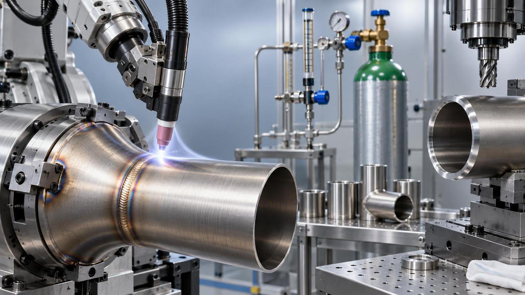
Thin-wall titanium tubing—especially in aerospace, medical, and high-performance fluid systems—demands weld integrity that leaves no margin for error. Porosity, micro-cracking, or heat-induced distortion aren’t just cosmetic flaws; they compromise pressure containment, fatigue life, and regulatory compliance. A robotic TIG welder alone doesn’t guarantee success. What separates repeatable, code-compliant welds from scrap is not hardware capability alone, but precise, context-aware setup: gas flow calibration tailored to joint geometry and ambient conditions; torch angle adjusted not by degree alone, but by its direct effect on arc column constriction and melt pool dynamics; and arc stability maintained under low-amperage, high-impedance conditions where conventional parameters fail.
Gas flow must shield—not sweep. For titanium, even brief oxygen exposure above 400°C initiates embrittlement. Standard flow rates quoted in manuals (e.g., 15–25 L/min) assume open-air, flat-plate welding with laminar flow and no turbulence. Thin-wall tubing introduces three compounding variables: restricted access (often requiring extended nozzles or gas lenses), curved surface geometry disrupting gas envelope symmetry, and convection currents from part rotation or fixture heating. Flow too low fails to displace air at the trailing edge of the weld pool; flow too high creates turbulence that pulls ambient air into the shield zone—particularly at the root side of a butt joint on 0.5–1.2 mm wall thickness. Calibration starts with a baseline: use a flowmeter calibrated for argon at operating pressure, not the regulator gauge. Then conduct a *shielding integrity test*: weld a short bead on scrap tubing under identical joint prep and travel speed, then section and etch the root. Any discoloration beyond pale straw indicates insufficient shielding. Adjust flow in 2 L/min increments—and retest—until root color remains uniform light gold. Note: if using a trailing gas shield (common for orbital or circumferential welds), its flow must be 30–50% lower than the primary nozzle to avoid back-pressure interference.
Torch angle isn’t about comfort—it’s about energy vector control. A perpendicular torch (90°) maximizes current density but minimizes arc column length, increasing sensitivity to minor standoff variation and promoting excessive penetration in thin walls. A 15°–20° forehand angle (torch tilted in direction of travel) elongates the arc, spreads heat input over a wider zone, and improves filler wire wetting—critical when using cold-wire feed systems common in robotic setups. But this comes at a cost: reduced penetration depth and higher risk of incomplete fusion at the root if travel speed isn’t synchronized. The optimal angle emerges only when matched to joint fit-up tolerance. For tubing with ±0.1 mm gap variation, a 12°–15° angle paired with a slight arc voltage boost (+0.5–1.0 V) stabilizes the arc footpoint without sacrificing fusion. Conversely, for laser-aligned, zero-gap joints, a 7°–10° angle maintains sufficient penetration while minimizing heat buildup in the heat-affected zone (HAZ). Never lock angle based on fixture position alone—verify with macro-etched cross-sections showing consistent root reinforcement and absence of underfill.
Arc stability at low amperage (40–90 A DCEN) is where many robotic systems falter—not due to power source limitation, but because of impedance mismatch between torch, cable, and workpiece return path. Titanium’s low thermal conductivity concentrates resistive heating at the arc attachment point. If the ground clamp isn’t placed within 150 mm of the weld start, or if the return path includes painted surfaces, rust, or multi-point fixtures, voltage fluctuations exceed ±1.5 V, causing arc wander and inconsistent bead width. Stabilization begins before ignition: verify all connections—torch collet, back cap, ground clamp—are clean, tight, and free of oxide. Use copper-braided ground cables rated for ≥200 A continuous duty, even for low-current applications. Then perform an *arc responsiveness test*: initiate arc at 50 A, hold for 3 seconds, then ramp to 85 A over 1 second. A stable system shows ≤0.3 sec delay in current rise and no visible arc deflection. If instability occurs, check for electromagnetic interference from nearby servo drives—shielded torch cables and separate conduit routing for power and signal lines are non-negotiable.
Joint preparation quality directly governs whether setup refinements matter at all. Milling the tube ends prior to welding isn’t optional—it’s foundational. An uneven or oxidized cut surface forces the arc to compensate, destabilizing heat distribution and inviting porosity at the root. This is where precision edge preparation becomes a prerequisite, not a parallel task. A machine like the Edge milling machine ensures consistent squareness and surface finish across batches—critical when feeding tubing into robotic fixturing. Its micron-level accuracy in forming straight edges and controlled bevel angles eliminates variability introduced by manual grinding or plasma cutting, reducing pre-weld inspection time and rejecting fewer parts downstream.
None of these adjustments exist in isolation. Increasing gas flow without adjusting torch angle may cool the leading edge excessively, causing cold lap. Reducing amperage to limit distortion without verifying arc stability may yield a narrow, brittle bead prone to cracking under thermal cycling. The goal isn’t to optimize each parameter separately, but to identify the *interdependent window*—a narrow band of combined settings where gas coverage, heat distribution, and electrical consistency converge. That window is defined not by theory, but by destructive testing: sectioning, macro-etching, and bend testing per AWS D17.1 or ASTM B366. Operators who skip this validation step often mistake repeatability for reliability—running identical programs on multiple shifts while undetected micro-defects accumulate.
Finally, recognize that robotic TIG on titanium is less about automation and more about disciplined process control. The robot removes human tremor—but it amplifies every inconsistency in consumables, grounding, gas purity, or fixture rigidity. A single batch of contaminated tungsten, a worn collet body, or argon with >30 ppm oxygen will invalidate even the most meticulously calibrated setup. Daily verification—gas purity checks, tungsten tip geometry inspection, and ground resistance measurement (<0.1 Ω)—isn’t maintenance overhead. It’s the operational floor beneath weld integrity.
search
Products Navigation
Send Us A Message