




Robotic TIG Welding Best Practices for Medical Device OEMs: ASME BPVC Section IX Qualification Paths & Micro-Weld Traceability
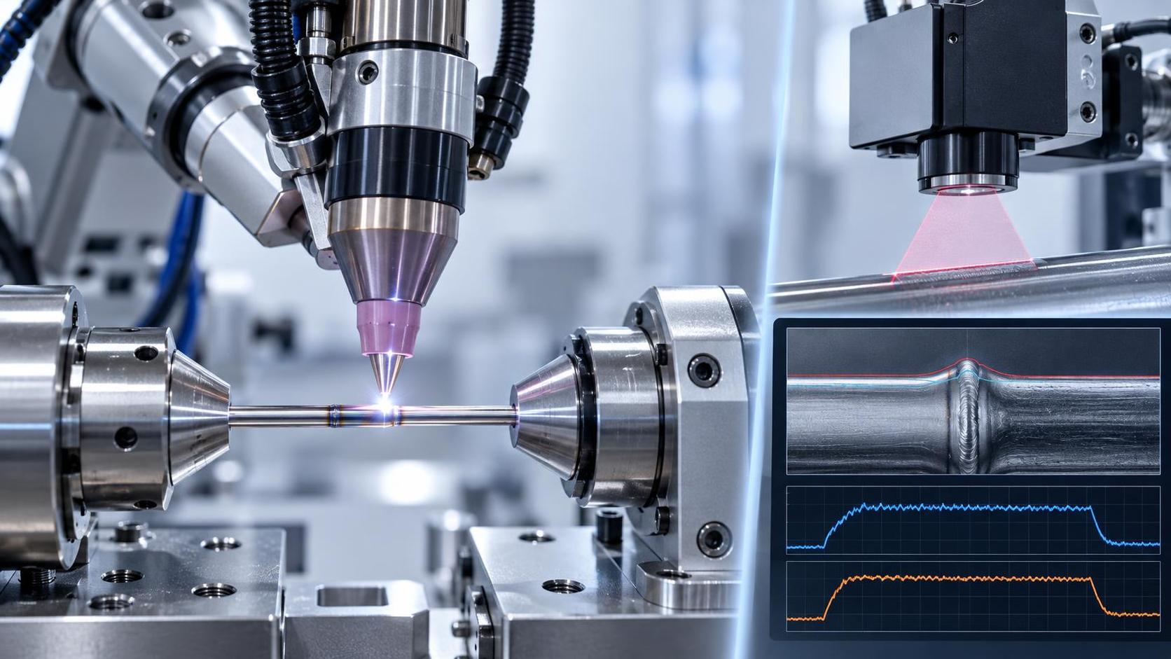
When Robotic TIG Welding Isn’t Enough—What Medical Device OEMs Overlook in ASME BPVC Section IX Qualification
For quality and safety professionals at medical device OEMs, robotic TIG welding isn’t evaluated on cycle time or electrode consumption—it’s judged by whether each weld passes the audit trail, survives destructive testing, and holds up under sterilization, fatigue, and long-term implantation. Yet many teams treat ASME BPVC Section IX qualification as a one-time paperwork exercise: “We qualified the procedure, trained the operator, and ran the PQR.” That approach fails—not because the weld is technically unsound, but because it lacks traceability to the micro-scale conditions that define clinical acceptability.
The Hidden Gap: Section IX Covers Process, Not Micro-Weld Integrity
ASME BPVC Section IX governs welding procedure qualification (WPQ) and welder performance qualification (WPQ). It validates that a given set of parameters—current, voltage, travel speed, gas flow, tungsten geometry—can produce sound welds within defined ranges. But for medical devices, “sound” means more than absence of porosity or cracks. It means consistent heat input across 0.3-mm-thick stainless steel tubing joints; uniform fusion depth in titanium alloy housings with thermal mass gradients; repeatable arc stability during 8-second welds on nitinol components where 0.1 second of arc wander shifts grain structure beyond ISO 13485 acceptance limits.
This is where robotic TIG systems diverge from traditional qualification logic. A Section IX-qualified procedure may allow ±15% variation in amperage—but for a 1.2-mm-diameter vascular connector, ±3% exceeds allowable HAZ width per ASTM F2516. The standard doesn’t require logging real-time current deviation at 100 Hz, nor does it mandate correlation between arc voltage spikes and subsequent tensile test outliers. Yet those correlations are what regulators examine when reviewing design history files for Class III devices.
Three Non-Negotiable Traceability Requirements—Beyond Section IX
True compliance starts where Section IX ends. Here’s what auditors now routinely inspect—and why generic robotic TIG platforms fall short:
- Parameter lock-in at sub-cycle resolution: Not just “average amperage = 75 A,” but full waveform capture (voltage, current, arc length) synchronized with robot path coordinates, sampled ≥1 kHz. Without this, you cannot correlate a 200-ms dip in shielding gas flow with localized oxidation in a single 3-mm seam segment.
- Material lot-to-weld linkage: Section IX assumes homogeneous base metal. In reality, a single batch of 316LVM tubing may have minor variations in nitrogen content affecting ferrite number. Traceability must bind each weld segment to incoming material certs, heat treatment logs, and post-weld cleaning validation—not just part number and revision.
- Micro-geometry verification integrated into process control: A qualified procedure doesn’t guarantee consistent penetration in 0.4-mm-thick endoscopic sheath walls. You need inline monitoring—e.g., laser profilometry synced to weld start/stop triggers—that flags deviations >±0.02 mm in reinforcement height before the part leaves the station.
These aren’t “nice-to-haves.” They’re embedded in FDA’s 21 CFR Part 820.70(a) (“production processes must be adequately controlled”) and reflected in recent MDSAP audit findings where 63% of nonconformities related to insufficient weld parameter traceability—not weld defects themselves.
Qualification Pathways: Which One Fits Your Device Risk Profile?
There is no universal Section IX path. The right choice depends on your device’s risk classification, geometry complexity, and production volume:
Note: The third path—qualified robotic system—is increasingly required for Class III devices. It treats the robot, power source, torch, cooling unit, and vision system as an integrated manufacturing unit. You don’t qualify “TIG welding”—you qualify this specific configuration, validated against actual production parts, not coupons. This is where ISO 9001-compliant design rigor matters: systems built to CE and ISO 9001 standards embed calibration traceability, firmware version control, and secure parameter logging by architecture—not as an afterthought.
Where Thread Integrity Supports Weld Integrity—A Practical Link
Weld integrity doesn’t exist in isolation. Consider fastening: a pacemaker housing sealed with robotic TIG must also accommodate precision-threaded feedthroughs. If those threads are cut—not rolled—they introduce micro-notches, residual tensile stress, and variable surface finish—all factors that accelerate fatigue failure at weld-adjacent interfaces. Cold rolling, unlike cutting, produces compressive surface stress and eliminates micro-crack initiation sites. For high-strength fasteners used in hermetic enclosures, the Z28-500 thread rolling machine delivers threads with Ry 0.1–0.8 μm roughness and full profile consistency—critical where thread root geometry directly influences cyclic loading at welded flanges.
This isn’t cross-selling. It’s systems thinking: weld qualification fails if adjacent processes undermine joint reliability. A robust Section IX strategy accounts for how every mechanical interface—including threaded assemblies—interacts with thermal cycles, sterilization stresses, and long-term corrosion resistance.
Next Steps: What to Audit Before Your Next 510(k) Submission
Don’t wait for the auditor to ask. Conduct an internal readiness check on these three items:
- Parameter log granularity: Can you retrieve archived data showing current/voltage waveforms for any weld made in the last 18 months—not just summary reports?
- Change control linkage: When a robot firmware update altered arc ignition timing by 12 ms, was a new PQR triggered—or was it documented only in the software release log?
- Material traceability scope: Does your WPS reference ASTM F138 lot numbers—or just “316L stainless steel”? If the latter, your qualification is incomplete for implantables.
Robotic TIG welding in medical manufacturing isn’t about automation for automation’s sake. It’s about building evidence—not just welds—that withstand scrutiny at every scale: macro, micro, and regulatory. The most effective qualification paths don’t minimize effort; they eliminate ambiguity. And that starts with treating each weld not as a process output, but as a documented, bounded, and verifiable clinical event.
search
Products Navigation
Send Us A Message