




Rotary Draw Bending vs Roll Bending: Which Fits Tight-Radius Tube Work?
Rotary Draw Bending vs Roll Bending: Which Fits Tight-Radius Tube Work?
The main mistake in this comparison is treating rotary draw bending and roll bending as interchangeable ways to curve tube. They are not. When a job calls for a tight centerline radius, controlled orientation, and repeatable geometry from part to part, the process choice is already narrowing before anyone discusses price. That is why rotary draw bending keeps coming up in technical evaluations for exhaust systems, handrails, furniture frames, hydraulic lines, structural tube assemblies, and fabricated machine components where the bend is a defined feature rather than just a general curve.
Roll bending has its place, and in many shops it is the more practical answer for large-radius arcs, sweeping profiles, and ring-type work. But once the radius becomes tight relative to tube diameter, the limits of the process become easier to see. The issue is not simply whether the tube can be bent. The issue is whether it can be bent to the required shape, with acceptable ovality, surface condition, springback control, and positional accuracy, without creating a setup that is unstable or too dependent on operator correction.
What really separates the two processes
Rotary draw bending forms the tube around a fixed-radius bend die. The tube is clamped and drawn around that die, often with pressure dies and, when needed, internal support such as mandrels or external wiper assistance depending on wall thickness, material, and quality requirements. That matters because the bend radius is not being “approached” gradually. It is being defined by tooling.
Roll bending works differently. Three rollers, or sometimes more in specialized systems, progressively feed and curve the material. The radius is developed incrementally through pressure and repeated passes. This is efficient for broad radii and long, smooth curves, especially where exact bend tangents are less critical than achieving an overall profile. In tube and profile work, that can be a very useful production method. It is just not inherently optimized for tight-radius features.
That distinction explains most of the downstream differences. Rotary draw bending is a geometry-control process. Roll bending is a progressive-forming process. If the design intent is a precise bend at a known location, those are different conversations from the start.
Why tight-radius tube work usually points toward rotary draw bending
A tight-radius bend increases strain on the outer wall and compression on the inner wall. The tighter the bend relative to diameter and wall thickness, the harder it becomes to avoid flattening, wrinkling, wall thinning, and loss of dimensional control. Rotary draw bending addresses this with dedicated tooling and controlled restraint. That is the core reason it is preferred for demanding tube work.
For technical evaluators, four criteria usually matter more than the headline bend radius:
The practical takeaway is straightforward. If a print specifies a short tangent, a compact bend, and close downstream fit-up, rotary draw bending usually gives the cleaner route to compliance. If the requirement is a broad arc with less emphasis on exact bend initiation and termination points, roll bending may be simpler and more economical.
Where roll bending still makes sense
Dismissing roll bending would be a mistake. It remains the right process in many fabrication environments, especially where the part is defined by curvature over length rather than by one or two compact bends. Architectural sections, frames, guards, large tubular supports, and ring-type components often fall into this category. For those parts, the ability to feed material continuously and develop a radius without dedicated bend dies can be a real advantage.
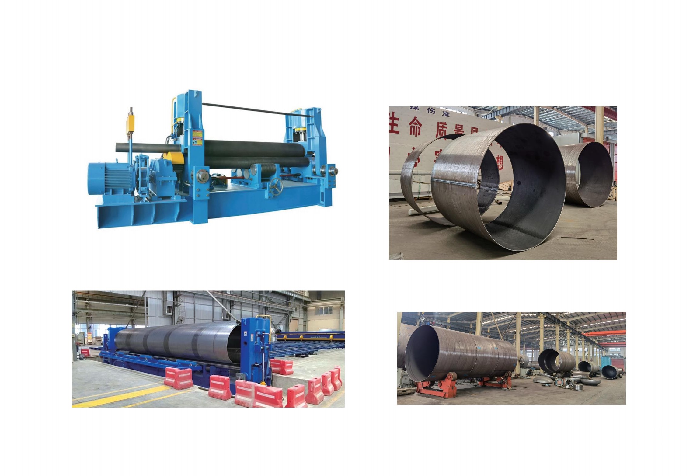
This is also why the wider forming equipment landscape matters. In heavier fabrication, shops often evaluate bending technologies side by side rather than in isolation. A machine such as Mechanized bending machine with 3 roller is intended for metal fabrication tasks involving steel and thicker plate, including cylindrical, conical, elliptical, and arc-shaped workpieces. That is not tube rotary draw bending, but it reflects the same selection logic: roller-based forming is highly effective when the geometry is developed progressively and the workpiece scale favors rolling over die-defined bending. For plate thicknesses of 50 mm or more, that kind of arrangement can offer the stability and accuracy needed in large-format production.
The important point is process fit. Rolling is not inferior; it is optimized for a different shape problem.
Common misunderstandings in process selection
One common misunderstanding is assuming that if a roller can eventually force the tube into a smaller radius, it is therefore suitable for tight-radius production. In evaluation work, “suitable” has to include repeatability, scrap rate, setup time, and the consistency of the finished section. A one-off bend achieved with operator adjustment is not the same as a controlled production process.
Another is focusing only on outside appearance. A bend may look acceptable from a distance while still showing excessive ovality, inconsistent leg length, or wall reduction that creates trouble during assembly or service. This becomes more serious in components that connect to fixtures, seals, mating tubes, or robotic weld cells where positional drift accumulates quickly.
There is also a tendency to compare machine tonnage or general machine size instead of comparing how each process controls material flow. In tight-radius tube work, control of material flow is often more decisive than raw forming force. That is why tooling design, lubrication, support method, and material temper can matter as much as the machine platform itself.
What technical evaluators should check before deciding
Start with the ratio between bend radius, tube outside diameter, and wall thickness. That relationship determines whether the job is routine, marginal, or likely to require internal support and tighter process control. Then look at the material itself. Mild steel, stainless steel, aluminum alloys, and higher-strength tube do not respond the same way under tight bending conditions. Springback behavior and surface marking risk can change the machine recommendation.
After that, review the part as an assembly feature, not just a bend. Questions worth asking include:
- Does the bend need a fixed orientation relative to holes, end forms, or welded brackets?
- Are tangent lengths short enough to complicate clamping or support?
- Will section deformation affect flow, sealing, insertion, or cosmetic acceptance?
- Is production volume high enough to justify dedicated tooling?
- Will multiple bends in one part require indexed rotation and strict sequence control?
The more often the answer is yes, the more rotary draw bending becomes the likely candidate. Not automatically, but often enough that it should be the baseline process under review.
Production context matters too. Wuxi Samgins International Trade Co.,Ltd works across a broad range of fabrication and machine-tool equipment, including pipe benders, plate rolling machines, CNC systems, welding automation, and related machinery supplied to different overseas markets. In that kind of equipment environment, the recurring lesson is that process selection is rarely decided by a single parameter. Buyers who get the best long-term result usually compare forming method, tooling burden, operator sensitivity, and downstream fit-up together. That is especially true when ISO9001-managed production and CE-oriented equipment expectations push consistency higher than a simple “can it bend” threshold.
A useful way to frame the decision
If the part needs a precise bend, in a precise place, at a radius that is small relative to the tube size, rotary draw bending is usually the process to evaluate first. Its advantage is not that it bends everything better. Its advantage is that it gives tighter control when the bend itself is a critical engineered feature.
If the part is really a long, smooth curve, or a large-radius rolled section where exact bend start and stop points are less critical, roll bending often stays in the conversation for good reason. In adjacent heavy-forming applications, equipment such as the Mechanized bending machine with 3 roller shows how effective roller-based forming can be when geometry and material thickness align with that method.
For tight-radius tube work, though, the deciding question is not which process is more versatile in general. It is which one controls the specific failure modes your part cannot tolerate. Once that question is answered honestly, the gap between roll bending and rotary draw bending usually becomes much clearer.
search
Products Navigation
Send Us A Message