




Selecting a Handling Robot: Payload, Reach, Cycle Time, and End-Effector Criteria
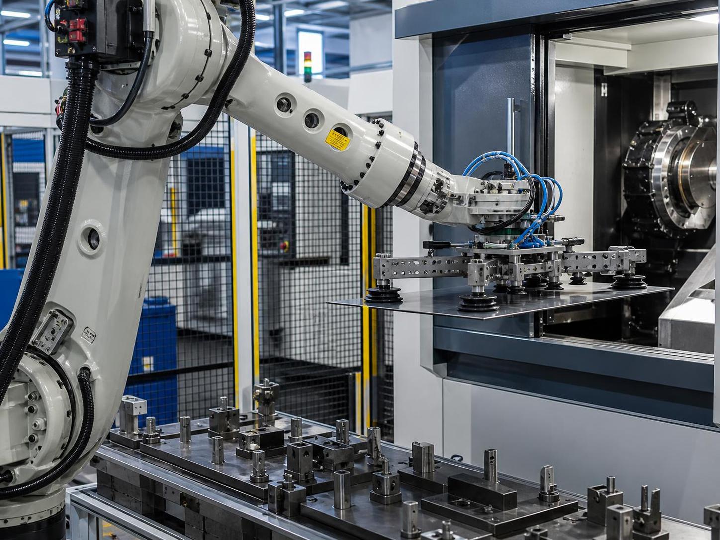
Selecting a Handling Robot: Payload, Reach, Cycle Time, and End-Effector Criteria
Selecting a Handling Robot is rarely a matter of choosing the model with the largest payload or fastest published speed. In a real fabrication, machining, welding, or material-preparation cell, the robot must move a particular part, with a particular tool, through a defined path, while remaining stable over thousands of cycles. A specification that looks sufficient on a brochure can become marginal once gripper weight, offset loads, cable routing, fixture access, part variation, and recovery movements are included.
For technical evaluators, the practical question is not “Which robot is bigger?” It is “Which robot can complete this process reliably, safely, and at the required production rhythm without creating a maintenance or integration problem?” Payload, reach, cycle time, repeatability, and end-effector design need to be assessed as one system. Separating them too early is one of the most common causes of oversized robots, underperforming cells, and costly redesigns.
Start with the Process, Not the Robot Catalogue
Before comparing robot families, define the handling task in operational terms. This includes the incoming part condition, weight range, dimensions, center of gravity, pickup orientation, destination, required placement tolerance, and what happens when a part is mispositioned. A robot loading steel blanks into a press brake faces a different set of constraints from one tending a CNC lathe, stacking cut plates, or transferring welded assemblies between stations.
The process map should include more than the nominal pick-and-place movement. Record where the operator loads material, how the part is presented, whether separators or oil create pickup difficulties, whether the machine door or safety fence restricts access, and whether the robot must wait for an upstream machine. In many cells, the limiting factor is not robotic motion. It may be clamp release, a conveyor index, a cutting-table unload sequence, or a manual quality check.
It is also useful to classify the workpieces by family rather than selecting around one ideal part. A handling system built only around the heaviest or largest component can be unnecessarily expensive for everyday production. Conversely, selecting around the average component may leave no usable margin for the jobs that actually drive downtime. The right design basis is normally the credible operating envelope: the parts expected to run regularly, plus the foreseeable exceptions that the cell must accommodate.
Payload Means More Than Part Weight
Rated payload is often misunderstood as the maximum workpiece weight. In reality, the robot carries the part, end-effector, mounting hardware, sensors, pneumatic or vacuum components, cable dress pack, and sometimes a quick-change interface. The relevant calculation is the combined mass at the wrist, together with the load’s center of gravity and inertia.
A light but long steel profile can be more demanding than a compact, heavier component because its center of gravity sits far from the robot flange. When the arm accelerates or stops, that offset creates a moment at the wrist and higher dynamic loading across the axes. Flat sheets produce a similar concern: their mass may be modest, but their size, flexibility, and tendency to deflect can limit acceleration and require a more carefully supported gripper.
Technical reviews should therefore request the robot manufacturer’s permissible wrist moment and inertia data, not just its payload rating. The robot supplier or integrator should verify the actual tool-and-part model against the intended duty cycle. This is especially important when grippers are still being designed. A robot selected with only a small static payload margin can quickly become unsuitable once a robust industrial gripper, valve island, collision sensor, and protective hardware are added.
Oversizing is not always the answer. A substantially larger robot may require more floor space, carry a higher purchase cost, and have less favorable performance for small parts. The aim is a defensible margin based on the real load case and motion profile, rather than a generic rule applied to every project.
Reach Must Be Validated in Three Dimensions
Maximum reach is another figure that can mislead. A robot may technically reach a location at the outer edge of its envelope, yet have poor joint angles, limited wrist freedom, reduced speed, or an unfavorable approach to the fixture. The usable work envelope is determined by the complete cell: robot pedestal, gripper geometry, machine opening, part rack height, guarding, maintenance clearance, and the locations of all process stations.
For machine tending, examine both the load and unload path. Can the robot enter the machine with a safe tool orientation? Can it clear chuck jaws, vises, probes, or internal guarding? Will the wrist approach singularity during insertion? For palletizing or stacking, check low positions as carefully as high positions; shoulder interference and reduced vertical access are common at the bottom layers of a stack.
A digital reach study is valuable, but it should represent real dimensions, not simplified blocks. Include cable routing, clamps, locating pins, and the actual gripper outline. Then test the worst-case parts at the most difficult station positions. This exercise often reveals that a modest pedestal adjustment, fixture rotation, or different rack arrangement can allow use of a smaller and more effective robot.
Cycle Time Is a System Calculation
Robot speed ratings do not equal cell throughput. Published axis speeds or standard cycle figures are useful reference points, but actual cycle time depends on travel distance, acceleration limits, payload inertia, path accuracy, gripper actuation, vision or sensor checks, machine interlocks, and the time required for the upstream process. A robot may finish its motion quickly and still wait several seconds for a door, fixture, or machine-ready signal.
Break the cycle into measurable events: part detection, pickup confirmation, travel, orientation changes, placement, release confirmation, return movement, and communication handshakes. Add the non-robot time. This makes it easier to identify where engineering effort will have the greatest effect. Reducing a long travel path, using dual grippers, or allowing the robot to prepare the next part during a machine cycle can be more valuable than selecting a robot with a higher nominal speed.
Do not evaluate cycle time only under ideal conditions. Include the effect of part variation, occasional retries, empty pickup checks, and safe-speed zones near operators or shared equipment. If a quoted cycle time relies on aggressive acceleration with a large offset load, confirm that the resulting vibration will not compromise placement or shorten gripper life. Stable repeatable motion is generally more useful than a theoretical peak rate that cannot be sustained.
The End-Effector Often Decides Whether the Cell Works
The end-effector is the direct interface between automation and the workpiece. Its selection should begin with the physics of the part: surface condition, porosity, temperature, sharp edges, oil, geometry, rigidity, and permitted contact areas. Vacuum cups can be highly effective for clean flat sheet, but may need vacuum monitoring and multiple zones where plate size varies. Magnetic grippers can suit ferrous materials, although surface scale, residual parts, and safe release need careful attention. Mechanical grippers may offer stronger positive retention but can introduce marking, deformation, or access constraints.
A sound gripper design answers several uncomfortable questions. What confirms that the part has been picked? What happens if a cup is blocked, a magnet contacts two parts, or a component is warped? Can the tool tolerate burrs and cut edges? Is there enough stiffness to prevent oscillation during travel? Can operators change wear parts without disturbing robot calibration? These details affect availability far more than an attractive robot specification.
For mixed production, quick-change tooling or a configurable gripper may be justified, but flexibility has a cost. Extra interfaces add mass, consume reach, and create more points that require inspection. A dedicated end-effector is often preferable where product variety is limited and throughput is critical. Where multiple part families are unavoidable, calculate each tool’s mass and center of gravity separately; the “standard” tool may not be the governing load case.
Repeatability, Accuracy, and the Fixture Relationship
Robot repeatability describes how consistently the arm returns to a taught position. It should not be confused with absolute accuracy in the facility coordinate system. In a fixed, well-designed cell, repeatability may be the more relevant measure because the robot can be taught relative to stable fixtures. Where incoming materials vary, stations move, or the robot must locate parts from a changing conveyor position, additional sensing, vision, or compliant tooling may be required.
Fixtures deserve the same scrutiny as the robot. A highly repeatable robot cannot compensate for a locator that accumulates scale, a bent support table, or a flexible rack. During acceptance planning, define the actual placement requirement: is the part merely being transferred, presented to a machine, located for welding, or positioned for a precision secondary operation? The answer determines whether mechanical guides are sufficient or whether closed-loop verification is necessary.
Integration Around Cutting and Fabrication Equipment
Handling automation is frequently evaluated alongside CNC cutting, welding, bending, and machining equipment. In these projects, the transfer system should be considered from the start, not added after the main machine layout is fixed. For example, a gantry cutting installation with a 4,000 to 7,000 mm railway span and a valid cutting width of 3,200 to 6,200 mm may produce parts that differ widely in size and handling behavior. The robot or auxiliary handling device must accommodate not only the finished profile, but also skeleton removal, cut-part separation, and safe collection zones.
Where carbon or low-carbon steel plate is processed, cutting method and edge condition can influence gripper selection. A system combining flame and plasma cutting may cover flame cutting thicknesses of 6–180 mm and plasma cutting thicknesses of 1–50 mm, depending on the plasma source. Thick parts may call for a different lifting strategy than thin nested blanks; narrow strips can flex, while heavy profiles require attention to center of gravity and collision clearance. Multi-torch straight-bar cutting, with configurations of up to 19 torches, can also change the downstream part flow substantially.
For evaluators planning an integrated fabrication line, equipment such as a Cnc flame cutting machine should be reviewed together with unloading logic, part identification, buffer capacity, and the next process. Cutting accuracy, nesting strategy, and the rate at which parts leave the table all affect whether robotic handling is practical and how much buffering is needed. A robot cannot restore flow if downstream stations have no capacity to absorb mixed parts.
Safety, Service Access, and Controls Are Selection Criteria
Safety design should be established during the concept phase. The appropriate safeguarding approach depends on risk assessment, part hazards, cell layout, operating modes, and applicable local requirements. Heavy parts, sharp cut edges, hot material, and stored pneumatic or magnetic energy deserve particular attention. A collaborative operating mode does not automatically make a handling application safe; the workpiece and end-effector can remain hazardous even when robot forces are limited.
Service access is less visible during procurement but matters after installation. Check access to gripper consumables, vacuum filters, cable routing, lubrication points where applicable, robot controller, machine interfaces, and safety devices. Confirm how faults will be diagnosed and who owns the interface between robot, end-effector, conveyor, and process machine. The best technical arrangement is one that a maintenance team can understand, reset, and maintain without repeatedly altering the validated program.
Wuxi Samgins International Trade Co., Ltd., established in 2012 in Wuxi, Jiangsu Province, works across equipment categories that commonly meet in fabrication cells: automatic welding equipment, CNC cutting machines, CNC machine tools and lathes, welding robots, H-beam production equipment, bending and shearing machines, deburring systems, and related machinery. That wider equipment perspective is useful when assessing interfaces rather than treating the robot as an isolated purchase. Production and design are organized in accordance with the ISO9001 quality system and EU CE standards, while final compliance requirements should always be confirmed against the destination market and complete cell configuration.
A Practical Approval Checklist
Before releasing a Handling Robot project, ask for documented confirmation of the combined payload, center of gravity, wrist moments, inertia, and all end-effector variants. Review a complete reach simulation using actual machine and fixture dimensions. Validate the cycle-time estimate as a sequence of robot and non-robot events. Define pickup confirmation, error recovery, and part-loss behavior. Finally, agree on acceptance conditions: representative parts, expected throughput, placement criteria, safety functions, utilities, controls interfaces, and responsibilities at commissioning.
A well-chosen robot is not necessarily the highest-capacity or fastest unit available. It is the one whose load case, workspace, motion profile, tooling, and surrounding process have been checked honestly. When those decisions are made together, automation becomes easier to commission and far less likely to disappoint once production begins.
search
Products Navigation
Send Us A Message