




What Power Supply Does a Welding Robot Typically Require?
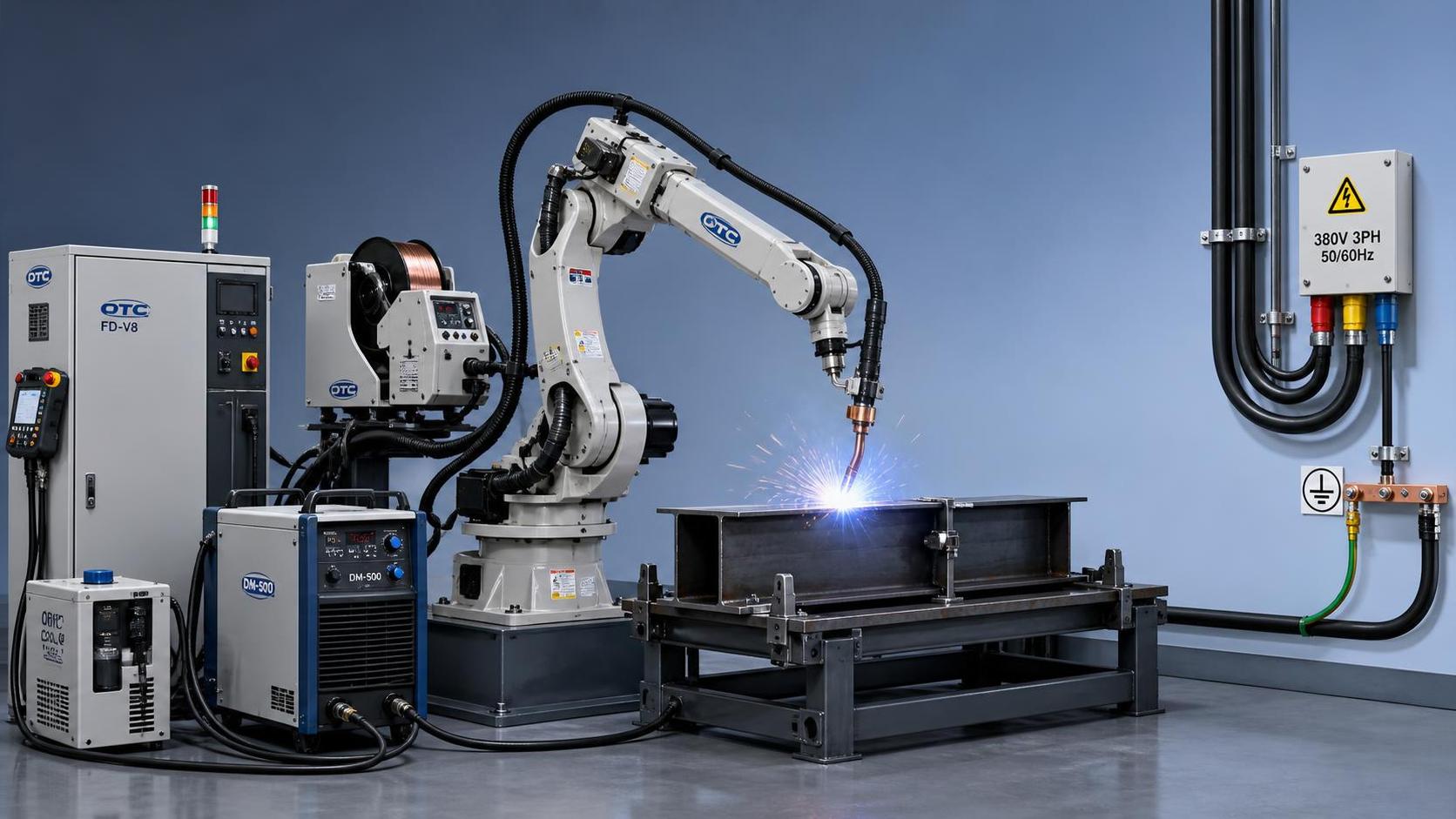
Most welding robots are installed on industrial three-phase power, and the exact voltage depends on the robot controller, the welding power source, and the country where the cell will run. In many factories, the robot controller may accept common industrial inputs such as 200-240V, 380-415V, 440V, or 480V AC at 50 or 60Hz, while the welding power source may have its own separate input requirement. Because of that, the practical answer to “What power supply does a welding robot typically require?” is usually a combination of two electrical loads: one for robot motion and control, and another for arc generation.
The robot itself does not usually consume power in the same way as the welding machine. Servo motors, control cabinet electronics, cooling fans, communication boards, safety circuits, and the teach pendant all need stable electrical input, but their demand is often far lower than the welding source. A MIG or MAG welding system can draw significant current during arc operation, especially when welding thicker carbon steel sections, fillet joints, or long continuous seams. TIG and plasma-related setups may differ, and spot welding systems can be much heavier electrically because the transformer load and peak current characteristics are very different from arc welding.
Controller power and welding power are usually specified separately
A common mistake is to ask for one voltage value as if the entire robotic welding cell uses a single electrical requirement. In practice, the robot arm is powered through its controller cabinet, and the welding process is powered through a welding source that may be integrated into the line but is still a separate electrical unit. Positioners, rotary tables, fume extraction, torch cleaning stations, seam tracking devices, and water cooling systems may also need their own feeds.
For that reason, a technical review normally starts with at least these items:
- robot controller input voltage and phase requirement;
- welding power source input voltage, frequency, and rated current draw;
- peripheral equipment load, including wire feeder, water cooler, and workpiece handling devices;
- starting current, peak load behavior, and whether the line power is stable enough for servo control and arc quality.
On many installations, the controller may use three-phase AC power and include internal transformers or switching power modules to supply lower-voltage DC circuits. The servo amplifiers then feed each axis motor. The welding source, by contrast, converts incoming AC to the controlled output needed for the welding process. That output is selected according to wire diameter, shielding gas, joint design, travel speed, and base material. Stainless steel, mild steel, and aluminum do not behave the same electrically during welding, so the source specification cannot be separated from the application.
Typical voltage ranges seen in robotic welding cells
When people ask, “What voltage and power supply requirements does a welding robot typically need?” they often want a practical reference range. The usual industrial range is three-phase AC power, with local plant standards determining the exact value. In some regions, 200-220V three-phase may be common for smaller systems. In others, 380V, 400V, 415V, or 480V three-phase is more normal for automated equipment. Single-phase power is generally unsuitable for the main robot system, except possibly for small auxiliary devices or maintenance tools.
The frequency also matters. A controller designed for 50Hz may not be interchangeable with one intended only for 60Hz unless the electrical design explicitly allows both. Many modern industrial controllers and inverter-based welding sources can accept 50/60Hz input, but this must be confirmed in the equipment documentation rather than assumed from appearance or cabinet size.
Voltage tolerance is another issue that is easy to overlook. A factory may nominally supply 400V, but the actual line can rise or fall under heavy load, particularly when large motors, compressors, or resistance heating equipment start nearby. If the robot controller or welding source has a narrow acceptable input range, nuisance faults, unstable arc starts, or communication resets can appear even though the nominal voltage seems correct on paper.
Power demand depends heavily on process type
A robotic MIG welding cell for medium-thickness structural steel usually has a very different electrical profile from a robotic TIG cell for thin stainless assemblies. MIG and MAG systems often need higher overall power input because the process is widely used for production welding with continuous wire feed and higher deposition rates. If pulse welding is used, the source may have additional control requirements, although the average load still depends on weld schedule, duty cycle, and actual output settings.
TIG robotic welding can demand cleaner process control and may involve lower welding current in some thin-wall applications, but the cell can still require stable industrial power because robot motion accuracy, arc start reliability, shielding gas control, and optional cooling circuits all depend on consistent input. Aluminum welding introduces another layer because wire feeding, torch cooling, and process stability often become more sensitive than in standard carbon steel work.
Spot welding robots are a separate category. Their electrical demand is often much higher than that of arc welding robots because the welding transformer and short-duration current peaks are substantial. In those cases, the main supply design must consider transformer sizing, busbar capacity, grounding, and line disturbance more carefully than in a standard arc welding station.
Rated power is not the same as installed load
Nameplate power is useful, but it does not automatically tell you how the cell behaves during production. Some devices draw relatively little power in standby and much more during acceleration, wire feeding, arc ignition, or high-duty operation. The robot arm may idle between welds, while the welding source cycles according to the program path. A system welding short intermittent beads on light fixtures will load the supply differently from a system running long seams on box columns, pressure parts, or fabricated frames.
That is why electrical planning usually looks at both rated input and operating pattern. If a controller cabinet is sized correctly but the feeder line, breaker, or cable cross-section is too small, voltage drop can become a hidden problem. The issue may appear first as erratic wire burnback, unstable arc starts, or random servo alarms rather than as an obvious power failure.
In longer cable runs, conductor sizing becomes especially important. Resistance in the supply cable can increase voltage drop under load, and poor termination quality at lugs or terminals can create heat buildup. In a welding environment, where dust, vibration, and temperature cycles are common, electrical joints should not be treated as a one-time installation detail.
Grounding and shielding affect performance
Power supply requirements are not limited to voltage and amperage. Proper grounding is part of the electrical requirement for reliable robotic welding. The robot controller, welding source, workpiece ground, and any sensitive communication equipment need an earthing arrangement that matches the equipment design and local code. Weak grounding can contribute to arc instability, sensor noise, touch sensing errors, and damage risk during electrical faults.
The welding return path also deserves attention. In arc welding, high current must return from the workpiece to the source through a path with low resistance and secure connection. If the ground clamp is attached poorly, or if painted, scaled, or rusted surfaces reduce conductivity, welding performance can degrade. This is not strictly the same as the facility protective earth, but both influence overall electrical behavior in the cell.
Cable routing matters too. Signal cables for encoders, fieldbus communication, and seam tracking sensors should not be laid carelessly alongside high-current welding cables if the installation guide warns against it. Electromagnetic interference can cause intermittent faults that look like software issues but originate in the power and wiring layout.
Installation conditions change the real requirement
Factory power availability can be very different from the machine specification sheet. A welding robot may be compatible with the plant voltage, yet the installation still needs a step-up or step-down transformer if local supply does not match the controller or welding source. Exported equipment often reaches sites where the standard plant voltage differs from the original build configuration, so this point should be checked before shipping rather than after the machine arrives.
Ambient temperature and ventilation also influence electrical reliability. Controller cabinets and welding power sources generate heat, and if they are installed near furnaces, enclosed too tightly, or exposed to metallic dust without proper filtration, internal temperature can rise and reduce component life. A power problem is sometimes diagnosed first, even though thermal stress is the real cause of repeated shutdowns.
Moisture and conductive dust can further complicate things. In fabrication shops cutting carbon steel, stainless plate, or aluminum, airborne particles may enter cabinets if seals are damaged or maintenance is neglected. Over time, contamination can affect terminals, fans, cooling passages, and printed circuit boards. The supply voltage may be perfectly correct while the equipment still shows electrical instability.
Before ordering, the electrical questions need to be very specific
“What voltage does it need?” is too broad unless it is broken down by subsystem. The practical questions are narrower:
- Does the robot controller require three-phase 380-415V, 480V, or another range?
- Is the welding source supplied from the same incoming line, or from a separate protected circuit?
- Will the process be MIG, MAG, TIG, or spot welding?
- Are there water coolers, positioners, slides, or turntables that add electrical load beyond the robot and welder?
- Does the equipment support both 50Hz and 60Hz operation, or only one?
- Will a transformer be needed after transport to the final site?
Those details affect cabinet design, cable preparation, breaker selection, and commissioning time. They also influence container loading and site installation planning, because a cell that needs external transformers, heavy-gauge cables, or additional cooling hardware may require different layout space and utility routing than expected.
Common misjudgments during setup
One frequent error is matching only the robot arm model and ignoring the controller revision. Two robots that appear similar mechanically may have different cabinet requirements. Another is assuming that because a manual welding power source worked on a given line, the robotic source will behave the same way. Robotic welding often introduces continuous duty cycles, communication interfaces, and synchronized motion control that place different demands on the electrical system.
Another misjudgment involves underestimating auxiliary equipment. Torch cleaning units, anti-spatter spray systems, fume extraction starters, safety PLCs, light curtains, and powered fixtures may not consume as much as the welder itself, but together they can change circuit loading and panel design. In compact cells, installers also sometimes leave insufficient service access around the controller and source, making future maintenance harder and increasing the chance of overheated cabinets.
There is also confusion between output welding current and input supply current. A welding source set to a certain welding amperage does not mean the facility needs to provide the same number as input current. The source converts power internally, and efficiency, power factor, and duty cycle all affect the relationship between welding output and mains input. The nameplate and manual remain the reliable reference.
Maintenance has an electrical side as well
Once the robot is running, power-related maintenance should be routine rather than reactive. Terminal tightness can change over time because of vibration and heat cycling. Fan filters in the controller cabinet and welding source may clog with dust, reducing cooling and creating trips that look electrical. Ground points should be inspected for oxidation, especially where the cell works on heavy fabricated parts with scale, oil residue, or frequent fixture changes.
Power quality problems may show up gradually. Arc start inconsistency, unexplained controller resets, or communication faults between the robot and welding package can all justify checking input voltage under load, not just at idle. In some plants, the issue only appears during operation of nearby equipment such as large compressors, presses, or plasma cutting systems.
If the cell is moved to another workshop or another country, the electrical review should be repeated from the beginning. Reusing the same machine does not guarantee that the same wiring, breaker values, grounding arrangement, or transformer configuration will remain suitable.
So, what power supply does a welding robot typically require? In most industrial settings, it requires a properly grounded three-phase AC supply matched to the robot controller and a separate welding power source specification matched to the welding process. The useful answer is never a single voltage number by itself. It is the complete electrical fit between controller, welder, peripherals, cable sizing, frequency, grounding, and the actual production duty the cell is expected to handle.
search
Products Navigation
Send Us A Message