




What to Check Before Buying a Plate Drilling Machine with CE
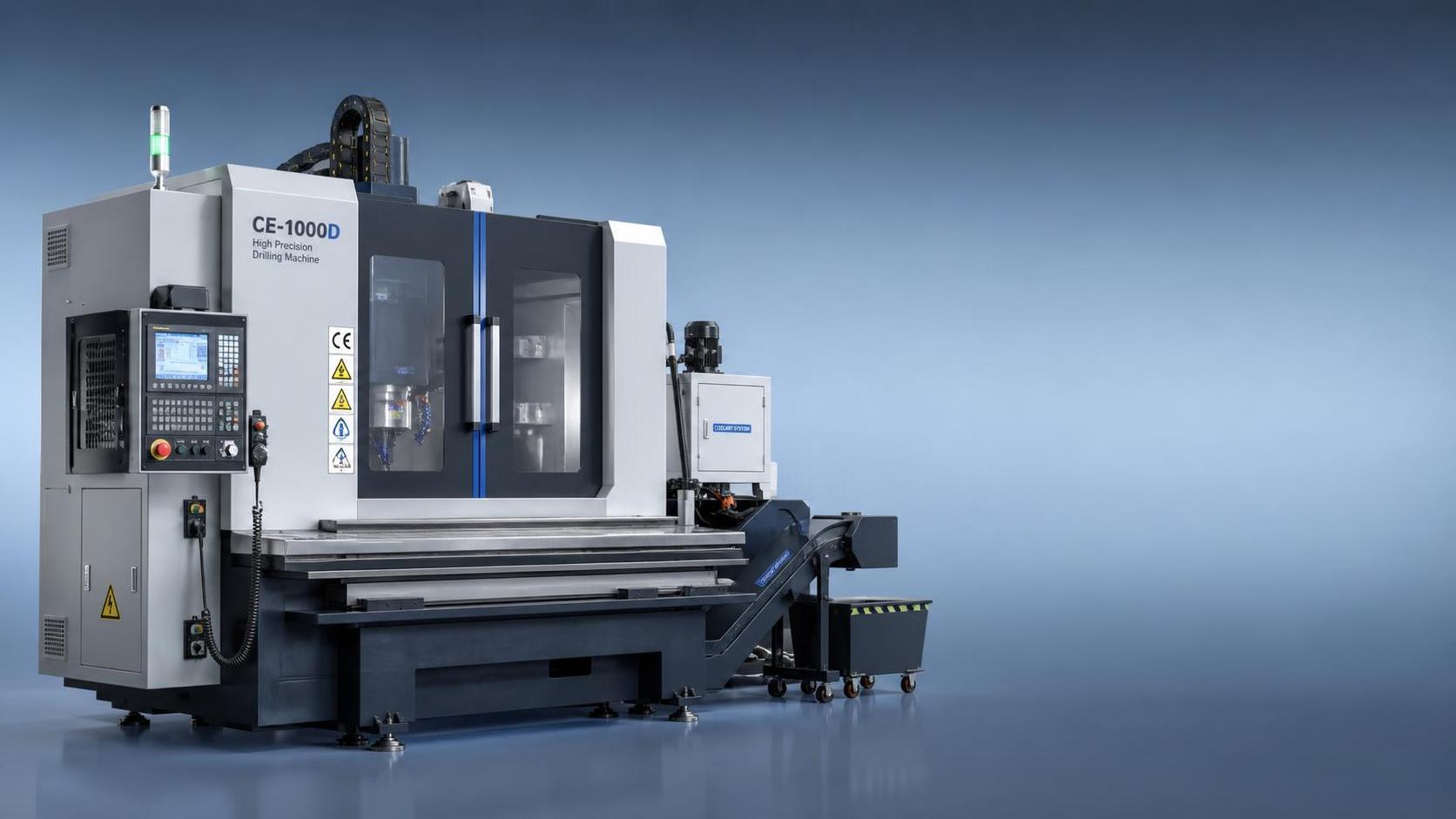
CE marking on a plate drilling machine should be treated as the starting point, not the final proof of safety or suitability. A machine may carry a CE label while still leaving gaps in documentation, guarding details, control logic, or installation assumptions. Before any technical discussion about spindle power or drilling diameter, the declaration, manuals, and electrical information need to match the exact machine configuration being offered, including optional CNC units, hydraulic clamping, chip conveyors, coolant systems, and automatic tool changers if those are part of the scope.
The Declaration of Conformity should identify the equipment clearly enough that there is no doubt about which model it covers. Basic items such as machine model, serial reference, manufacturer identity, applicable directives, and the responsible signatory matter because vague paperwork can hide configuration changes. If the offered plate drilling machine with CE has been modified for a different voltage, added guarding, a different control cabinet, or an imported spindle package, those changes should be reflected consistently across the declaration, nameplate, electrical drawings, and user manual. A mismatch between the machine plate and the paperwork is often a stronger warning sign than an obvious cosmetic defect.
Documentation Quality Often Reveals the Real Standard
Read the manual as a technical control document, not as sales literature. The useful manual is the one that states residual risks, lockout points, lubrication intervals, allowable plate dimensions, maximum workpiece weight, coolant recommendations, and fault-reset conditions in plain terms. If emergency stop devices are shown in one diagram but omitted from the operating description, or if maintenance instructions ignore guarding removal and restart conditions, the machine may have been documented only to satisfy shipment requirements. For drilling equipment, the manual should also define acceptable tooling, spindle taper or holder type, drilling depth limits, coolant use for different materials, and chip removal precautions for continuous operation.
Electrical schematics deserve the same level of attention. A compliant plate drilling machine with CE should have readable wiring diagrams, terminal identification, overload protection information, and clear marking of supply voltage and frequency. This matters in real operation because many installation problems are not caused by the frame or spindle but by unstable control power, incorrect phase sequence, unprotected cable routing, or poorly labeled field wiring. If the machine is intended for 220V, 380V, 480V, or 600V supply options, the installed components should match the ordered version exactly; the same applies to 50Hz or 60Hz frequency.
Machine Structure and Stability
Plate drilling creates intermittent cutting loads, vibration, and chip accumulation, especially on thicker carbon steel plates or when drilling larger diameters at higher feed pressure. Structural rigidity therefore needs direct inspection. Column deflection, gantry stiffness, table flatness, rail support, and the integrity of welded or cast structural members all influence hole position accuracy over time. A machine that looks heavy is not automatically stable. Ask how the frame was stress-relieved, how guideways are aligned, and whether the base requires grouting or a reinforced foundation under certain plate weights.
Table design deserves close scrutiny. Machines that process steel plate for base plates, flanges, gussets, and connection members often rely on support rollers, worktables, or slatted beds. The support arrangement should prevent sagging of long or narrow workpieces. If the plate bends during clamping or drilling, hole perpendicularity and pitch accuracy can drift even when spindle movement appears normal. It is useful to confirm whether the support system is suitable for stainless steel, alloy plate, or coated materials, because surface damage, slipping, or poor magnetic holding may appear under some conditions.
Where magnetic clamping is used, the holding method should be evaluated carefully. Surface scale, paint, rust, plate flatness, and material thickness can reduce effective holding force. For that reason, any statement about maximum drilling diameter should be read together with the conditions under which the machine remains stable. A capacity value without workpiece condition limits is incomplete.
Accuracy Under Actual Working Conditions
No serious assessment of a plate drilling machine with CE ends with nominal travel and spindle speed. The more useful questions concern repeatability after warm-up, hole location tolerance across the full table area, and how the machine behaves when drilling sequences involve mixed hole sizes. Machines sometimes perform well on a short acceptance sample yet drift when the workpiece spans a wider area or when the spindle operates for several hours. Thermal growth, backlash, rail contamination, and tool wear compensation all affect the result.
For CNC plate drilling machines, interpolation accuracy and datum setting procedures should be checked alongside mechanical performance. It helps to confirm how zero points are established, whether the system supports automatic edge finding, and how coordinate errors are handled after emergency stops or power interruptions. If the machine resumes a cycle after interruption, the control should make that recovery logic explicit. A hidden restart sequence can become a direct safety issue when the spindle, clamps, or plate positioning system reactivates unexpectedly.
Tooling interface details matter more than broad claims about productivity. Ask about maximum twist drill size, annular cutter range if applicable, tapping capability, spindle taper standard, coolant-through-spindle availability, and tool change verification. A machine used on structural steel plate may need one set of parameters, while stainless steel or thicker low-alloy material may require slower feed, stronger coolant filtration, and different chip evacuation behavior. Without that detail, the quoted drilling range says very little about actual process control.
Guarding, Interlocks, and Operator Exposure Points
Many weaknesses appear around moving parts that are considered routine: spindle zones, chip discharge areas, automatic tool changers, table travel paths, hydraulic clamps, and access doors for maintenance. CE marking should correspond to a risk reduction approach that can be observed on the machine itself. Fixed guards should not be easy to bypass without tools. Interlocked doors should stop hazardous motion reliably and should not permit casual defeat by simple alignment tricks. Emergency stop devices must be placed where a person can reach them from normal loading, setup, and troubleshooting positions rather than only from one side of the cabinet.
Chip control is not a minor housekeeping issue. Long, hot, sharp swarf from steel drilling can pull gloves, cut hoses, jam conveyors, and create slipping hazards around the machine. The machine should provide a realistic means of removing chips from the drilling zone without forcing manual intervention near rotating tools. Coolant splash containment, window material on enclosures, and the ease of cleaning underneath guards all affect day-to-day risk.
Where hydraulic or pneumatic systems are installed, look for pressure retention behavior, hose protection, valve labeling, and safe maintenance access. A clamp that drops pressure unexpectedly or remains energized after an abnormal stop can damage workpieces and create a hazardous condition during inspection or tool replacement.
Control System Behavior Matters as Much as Mechanical Build
Control panels should be legible, with alarm texts that identify faults clearly enough for controlled recovery. Generic alarms create unnecessary bypass behavior. A safer machine normally defines spindle overload, lubrication fault, servo alarm, clamp pressure abnormality, and limit overtravel separately. If the HMI language is incomplete or badly translated, that is not only an inconvenience; it may affect fault response accuracy and lockout practice.
Protection against unexpected restart is one of the first things to verify after a power dip or emergency stop reset. The spindle, coolant pump, table movement, and auxiliary units should require deliberate reactivation according to the control logic described in the manual. If the equipment includes remote functions, pendants, or external loading interfaces, their priority logic should also be clear.
This point becomes easier to evaluate when comparing the drilling machine with other automated equipment used in fabricated metal production. For example, an Welding manipulator intended for pressure vessels, pipelines, or steel structures often includes a defined anti-falling safety device, controlled lifting or extension movement, and a remote hand control box with predictable response. The same discipline should be expected from plate drilling equipment: hazardous motion needs to be controlled in a way that remains stable during setup, interruption, and maintenance, not only during ideal production runs.
Installation Conditions Should Be Verified Before Shipment
Transport and installation frequently introduce the first real deviations from factory acceptance. Machine dimensions, lifting points, transport locking arrangements, center of gravity, and floor loading requirements should be available in advance. If a plate drilling machine is assembled partly on site, the acceptance criteria for alignment, anchoring, and electrical connection should be written down. Otherwise, later disputes about vibration, noise, or accuracy may be impossible to resolve because the original installation condition was never defined.
Environmental conditions also deserve attention. Dust, welding fumes, grinding particles, temperature swings, and unstable compressed air supply can shorten component life and affect precision. In mixed fabrication shops, drilling machines are often installed near cutting, fit-up, or welding stations. If the enclosure sealing, cable routing, and cooling arrangement are not adequate, contamination will reach guideways, bearings, encoders, and electrical cabinets sooner than expected.
Power quality should not be assumed. Voltage fluctuation, grounding quality, and surge exposure can affect servo drives, PLCs, spindle inverters, and sensor reliability. Where a machine is ordered with multiple regional voltage options, component selection and transformer sizing should be checked against the final installation site rather than the quotation sheet alone.
Wear Parts, Serviceability, and Traceability
Long-term control depends partly on how easy the machine is to inspect and maintain without creating fresh risk. Lubrication points should be accessible. Filters, belts, coolant screens, proximity sensors, and spindle consumables should be replaceable without dismantling major guards or entering cramped pinch zones. If replacement parts are proprietary, it is worth confirming how part numbers are identified and whether electrical items, bearings, seals, and linear guide components are traceable to documented specifications.
Spare parts lists should separate routine consumables from critical safety-related parts. Limit switches, interlock devices, braking units, hydraulic valves, and emergency stop components should not be treated as generic afterthoughts. If the equipment uses branded controllers or inverters, compatibility of firmware and replacement modules should be addressed early, especially when the machine may be exported or relocated.
Maintenance intervals should reflect actual cutting duty. A machine drilling mild steel plate at moderate volume may tolerate one schedule, while intensive processing of thicker sections with coolant contamination and heavy chip load may justify shorter intervals. Manuals that provide only broad lubrication advice without reference to duty, environment, or symptoms are not strong enough for controlled operation.
Factory Acceptance Should Include More Than a Short Demo
A brief no-load movement test proves very little. More useful acceptance points include spindle runout, hole position verification on representative plate material, clamp performance, emergency stop response, lubrication confirmation, coolant circulation, alarm functionality, and restart behavior after interruption. If tapping, countersinking, or automatic tool change functions are included, those should be demonstrated under conditions close to expected use.
Noise and vibration should be observed during loaded cutting, not only during rapid traverse. Abnormal sound from the spindle head, guideways, gearbox, or hydraulic station may indicate alignment or assembly issues that do not appear in a static inspection. Surface finish around the drilled hole, burr condition, and chip form can also reveal whether feeds, rigidity, and coolant delivery are genuinely under control.
It is also reasonable to review how associated fabrication equipment is engineered, because consistency in safety thinking often shows up across machine categories. A well-designed Welding manipulator may specify vertical lifting stroke from 1000mm to 7000mm, controlled telescopic movement, and defined load limits at the boom, which makes capacity boundaries explicit rather than implied. A plate drilling machine should present its own limits with the same clarity: drilling range, workpiece dimensions, allowable thickness, loading method, and prohibited operations need to be stated without ambiguity.
One common mistake is to treat CE documentation, test cutting, and installation planning as separate topics. In practice they are linked. If the paperwork is loose, the control logic is hard to interpret, and the installation assumptions are vague, the machine may still run, but it will be difficult to manage safely and consistently. The better purchase outcome usually comes from aligning the declaration, drawings, guarding, accuracy evidence, and site conditions before shipment rather than trying to correct those gaps after the machine is on the floor.
search
Products Navigation
Send Us A Message