




How to Specify a Custom Plate Drilling Machine for Mixed Hole Patterns?
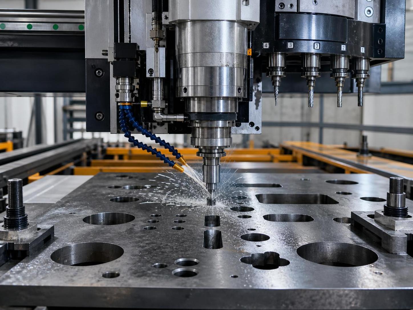
For mixed hole patterns, the specification should start with the pattern logic rather than with spindle power alone. A custom plate drilling machine that handles a few large holes, many small holes, slotted features, and changing edge distances in the same workpiece needs stable positioning, flexible programming, and predictable tool change behavior. If the plate layout includes clusters of closely spaced holes beside isolated large-diameter holes, the machine structure must resist vibration during rapid axis movement and maintain registration across the full working envelope.
The first point to define is the real plate range. Thickness is important, but plate length, width, flatness, material grade, and surface condition usually affect machine configuration just as much. Carbon steel, stainless steel, and alloy plate do not behave the same during drilling. Stainless steel may require lower cutting speed, stronger coolant delivery, and closer attention to chip evacuation. Thin plate can be harder to process than thicker plate when clamping is weak, because drill breakthrough may lift or deform the sheet. If the job mix includes flame-cut blanks or plasma-cut blanks, edge hardening and residual distortion should be considered before finalizing spindle load and hold-down arrangement.
Hole pattern complexity should be translated into machine motion requirements. A rectangular pattern with repeated pitch is straightforward. A mixed pattern with irregular coordinates, multiple diameters, countersinks, tapping points, and reference holes is different. In that case, the CNC needs to accept imported geometry reliably and allow operator correction without rebuilding the entire program. Machines with poor coordinate management often lose time during setup, especially when plates arrive with dimensional variation from upstream cutting. That is why the datum strategy matters: side reference, end stop, probing routine, or a combination of them.
Working Envelope and Usable Capacity
Do not specify table size only from the largest nominal plate. Consider the usable drilling area after clamps, side guides, chip conveyors, and tool approach limits are accounted for. A machine advertised for a certain plate width may offer less effective processing width once workholding is installed. If the pattern often reaches near the plate edge, ask for the true minimum distance from spindle centerline to clamp zone and machine frame obstruction. This affects whether edge holes can be completed in a single setup.
For long plates, support continuity is often underestimated. Unsupported sections can vibrate during drilling and produce poor hole finish or positional drift. Roller support, segmented tables, and intermediate supports may be needed if parts are narrow and long. When mixed hole patterns appear on gussets, base plates, connection plates, and stiffeners in the same production line, flexibility in support layout becomes more valuable than maximum table length alone.
Spindle and Tooling Choices
Spindle selection should follow the actual hole range and required finish. If most holes are created with carbide drills in moderate diameters, spindle speed stability and through-spindle coolant may matter more than peak torque. If larger holes are produced by annular cutters, low-speed torque and rigidity become more important. Some mixed pattern jobs combine pilot drilling, drilling, countersinking, and tapping. In that situation, the custom plate drilling machine should be reviewed as a process cell, not as a single drilling head.
Useful questions include whether the spindle supports automatic tool change, whether tool holders are standardized, and whether the control can manage tool life by count or by cutting time. For irregular production, manual tool change may seem acceptable, but the time loss becomes noticeable when the hole pattern contains many diameter changes. Tool magazine capacity should match the real part family. An oversized magazine is not automatically better, but too few stations can force repeated intervention.
Feed control at breakthrough is another detail that separates stable drilling from frequent burr and tool damage problems. Plates with mixed thickness zones or welded buildup can benefit from adaptive feed logic. Where tapping is required, spindle reversal quality and synchronization should be confirmed. Even when tapping volume is low, poor reverse control can break taps quickly in stainless or tough alloy plate.
Accuracy Depends on More Than Axis Resolution
Quoted positioning figures are not enough to judge actual hole quality. On plate drilling equipment, real output depends on frame rigidity, rail mounting accuracy, backlash control, servo tuning, spindle runout, and how the plate is restrained. A machine may state high axis precision yet still produce inconsistent hole spacing if chips accumulate under the workpiece or if the clamp layout allows movement during breakthrough.
When mixed hole patterns include mating holes for structural assembly, hole-to-hole relationship often matters more than absolute location relative to one plate corner. Ask how the builder verifies repeatability over a typical production cycle, not only under no-load movement. If acceptable hole tolerance is tight, the specification should also note whether reaming, interpolation, or secondary finishing is expected. Drilling alone may not be the final process for every hole class.
Chip evacuation should be treated as a quality issue, not only a housekeeping issue. Deep or repeated holes in carbon steel usually generate manageable chips, but stainless or gummy materials can produce long chips that wrap around the tool and affect hole wall finish. Through-spindle coolant, flood coolant direction, peck cycle flexibility, and conveyor access all influence whether the machine can hold quality without frequent stops.
Control System Behavior in Real Production
For a mixed-pattern workload, the CNC interface should allow quick editing at the machine. Holes may be added, deleted, resized, or shifted after nesting or after fit-up feedback from downstream assembly. If every small revision requires an external programming cycle, the machine loses practical value. Program recovery also matters. After a power interruption or tool break, the control should allow restart from a selected hole or process step with clear logic for spindle state, coolant, and coordinate confirmation.
This is also where upstream cutting quality enters the drilling specification. If plates are prepared on a Table type cnc plasma cutting machine, the resulting blank accuracy, heat-affected edge condition, and plate flatness can affect datum consistency and clamping behavior before drilling begins. For some thin to medium plates, a cutting system with about 1500 × 3000 mm cutting range, non-contact arc ignition, and accuracy around 0.2 mm/m may produce blanks suitable for direct transfer into drilling, provided the hole work is not being attempted in hardened edge zones and the locating faces are kept clean.
Software compatibility should be checked at a practical level. It is useful if the machine accepts common CAD/CAM outputs, but more important is whether the drilling cycle library supports the required operations without awkward workarounds. Slotting, chain drilling, staggered rows, mirrored patterns, and conditional repeat blocks are common in fabricated plate work. A clean simulation view is helpful, though simulation alone does not replace a reliable dry-run mode with clamp and travel verification.
Clamping, Referencing, and Plate Condition
Many specification errors begin with the assumption that the plate is flat and dimensionally stable. Real plates may arrive with mill scale, burrs, slight camber, thermal distortion, or weld spatter. Mixed hole patterns magnify these issues because the spindle travels across more zones of the plate and any local lift can influence hole location or surface finish. Clamps should be positioned to resist movement without blocking tool access. Pneumatic clamps are fast, hydraulic clamps offer stronger restraint, and manual clamping may be enough only for lower-volume or simpler work.
Vacuum workholding is generally less common for heavy steel plate drilling, but magnetic support or magnetic clamping may be considered for certain ferrous applications if plate thickness, surface condition, and safety interlocks are suitable. Where non-ferrous metals such as aluminum or copper are part of the mix, the workholding concept may need to change because magnetic assistance is unavailable. That should be reflected early in the custom machine layout instead of treated as a later accessory question.
Probe-based referencing can reduce setup error when blanks vary. However, probing is only useful if the software lets the operator apply the measured offset clearly and if the machine structure repeats after thermal growth. In a workshop with large daily temperature swings, long machines may show measurable expansion. This may not be a major problem for general fabrication, but it should be considered if the pattern contains fit-critical holes across a long span.
Production Rate Without Ignoring Hole Quality
Cycle time estimation should separate drilling time from non-cutting time. On mixed-pattern parts, rapid traverse, acceleration, clamp repositioning, tool changes, spindle orient, peck retraction, and deburring allowance can take a large share of total time. A fast spindle on paper does not guarantee high throughput if the axis system is slow between distant hole groups. Conversely, very aggressive rapid movement is not useful if the frame vibrates and forces conservative feed rates during actual drilling.
Some facilities process plate families that include both drilled components and profile-cut components. In such cases, line balancing may matter more than maximizing one machine alone. For example, if blanks are produced from stainless steel, carbon steel, aluminum, copper, titanium, or nickel on a profile cutting station such as the Table type cnc plasma cutting machine, the drilling machine should be specified with realistic assumptions about incoming part mix, plate flatness, and queue size rather than with a single-material benchmark.
Deburring should not be ignored during specification. Some mixed hole patterns involve assembly surfaces where burr height must be tightly controlled. If burr removal is required after drilling, confirm whether it will be manual, integrated, or handled in a separate machine. This changes not only cycle planning but also the required hole exit quality from the drill itself. For thin stainless, breakthrough burr can become the limiting issue even when hole diameter tolerance is acceptable.
Installation and Maintenance Factors That Affect Long-Term Use
Foundation condition, power supply stability, air quality, coolant management, and chip removal space all influence machine behavior. If the installation area has limited crane access, the machine bed and gantry dimensions during unloading should be reviewed before purchase. Large plate drilling systems may require staged assembly or alignment on site. That can affect commissioning time and the accuracy actually achieved after installation.
Maintenance access should be part of the specification, especially around guideways, lubrication points, spindle service area, cable carriers, and chip conveyor removal. Mixed-pattern production tends to create frequent program changes and varied cutting conditions, which means maintenance staff may need to inspect the spindle, coolant filters, and sensors more often than on a single-part production line. Spare parts strategy should focus on wear components and control hardware with realistic lead times.
It is also worth asking how the machine handles contamination from mill scale and hot-cut blanks. If plates come directly from thermal cutting, fine dust and oxide can enter linear guides and clamps unless protection is adequate. Bellows, covers, air purge arrangements, and coolant filtration deserve attention because poor contamination control often causes gradual accuracy loss rather than immediate failure.
Common Misjudgments During Specification
- Choosing by maximum drill diameter only. A machine that can produce one large hole may still perform poorly on a plate with frequent diameter changes, dense patterns, and tapping operations.
- Assuming all plate materials can share the same cutting data and coolant setup. Stainless, aluminum, and carbon steel impose different demands on chip control and tool life.
- Ignoring blank condition from upstream processing. Flame or plasma-cut distortion, burrs, and scale can reduce drilling consistency even when the drilling machine itself is properly configured.
- Focusing on nominal table dimensions without checking clamp interference, usable travel near edges, and support for long narrow parts.
- Underestimating restart logic after interruptions. In mixed hole patterns, a poor recovery sequence can scrap an otherwise salvageable plate.
A sound specification for a custom plate drilling machine ends up looking like a process description tied to real part geometry, material behavior, and shop conditions. Once those details are explicit, the machine configuration usually becomes clearer: working range, spindle type, tool change method, clamping layout, coolant arrangement, and CNC functions can then be selected on technical grounds rather than on headline specifications alone.
search
Products Navigation
Send Us A Message