




What to inspect before buying a robot welder for sale
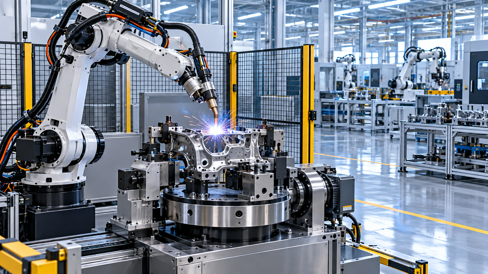
The purchase price of a robot welder is only the visible part of the investment. A lower-priced cell can become expensive when its reach misses a joint, its torch package limits movement, its fixtures require repeated adjustment, or a fault leaves production waiting for a replacement part. Before committing to a robot welder for sale, inspect the intended welds, part flow, installation conditions, and support scope as closely as the robot nameplate.
Start with representative production parts rather than a generic demonstration coupon. Provide drawings, material grades, thickness ranges, joint types, expected fit-up variation, and required weld appearance. A system that produces a clean fillet weld on a rigid, well-prepared sample may behave very differently on a fabricated assembly with gaps, tack weld variation, scale, oil, or inconsistent dimensional tolerances. The acceptance discussion should be based on the actual workpiece family and the quality criteria that apply to it.
Confirm that the robot can physically complete the weld
Payload and reach are often read separately, although they must be evaluated together. The listed payload must cover the complete moving load: welding torch, neck, wire feeder or wire package where applicable, torch cleaning accessories carried by the wrist, cables, dress pack, and any sensors. A robot operating close to its payload limit may still move, but acceleration, positional behavior, and long-term wear need examination under the planned tool configuration.
Reach also needs to be checked at the actual weld location, not merely against the robot's maximum radius. A joint near the floor, behind a flange, inside a box section, or around a rotating fixture may be within nominal reach while requiring an unfavorable wrist posture. At extreme reach, at axis limits, or near a singular wrist orientation, torch speed and angle control can become less practical. Review an offline simulation or a physical dry run that includes clamps, positioners, guarding, cable routing, and part loading space.
Axis travel limits are especially important for circular seams, long beams, and multi-sided fabrications. A robot may need to reorient midway through a weld if the positioner cannot present the joint properly. That interruption can create a restart mark, alter heat input, or increase cycle time. For large fabricated plate components, upstream blank preparation also affects robotic welding consistency. When cutting accuracy and edge condition govern fit-up, equipment such as a Gantry CNC plasma cutting machine may be relevant to the wider fabrication route, particularly where plate size, cut geometry, and edge quality influence the gaps delivered to the welding fixture.
Match the welding process to the material and joint
Inspect the proposed power source, wire feeder, torch, and controller as one process package. The robot arm does not determine weld quality by itself. Verify which processes are supported, such as gas metal arc welding, gas tungsten arc welding, flux-cored welding, or another specified process, and confirm that the configuration is suitable for the material and thickness range. Carbon steel, stainless steel, aluminum, and high-strength materials impose different requirements for wire selection, shielding gas, heat control, cleaning, and torch consumables.
Ask for the welding procedure range proposed for the work. This should identify base material condition, joint preparation, filler metal, shielding gas, current and voltage range, wire feed behavior, travel speed, torch angle, and interpass handling where relevant. Thick joints may require multiple passes and controlled sequencing. Thin sheet can distort when a fast robot repeats an unsuitable weld pattern. Aluminum demands attention to oxide removal and stable feeding, while galvanized material requires controls for fumes and weld contamination.
Do not treat a high travel speed as a direct measure of output. Deposition rate, arc-on time, positioning moves, wire trimming, torch cleaning, part turning, loading, and inspection all affect finished-part throughput. A cell with a slightly slower programmed weld speed may produce more acceptable parts when it avoids spatter buildup, incomplete fusion, rework, or frequent intervention. Compare complete cycle time from unloaded fixture to released part.
Look beyond a single weld sample
A useful trial includes the difficult conditions expected in production: the longest seam, an obstructed corner, a joint with the allowable fit-up tolerance, and a part after several consecutive cycles. Inspect bead profile, start and stop areas, porosity, spatter, undercut, overlap, burn-through, and evidence of unstable arc behavior. Where the required standard calls for it, agree on suitable examination methods before the trial. Visual appearance alone cannot establish fusion quality in every joint configuration.
Repeatability should be considered alongside accuracy. Published repeatability figures describe the robot's ability to return to a point under defined conditions; they do not compensate for a bent fixture, inconsistent component location, poor wire feeding, or changing torch geometry after a collision. If the workpiece datum changes from batch to batch, seam tracking, touch sensing, laser profiling, or adaptive programming may be necessary. Those options add capability, but they also introduce calibration and maintenance requirements that must be included in the evaluation.
Examine fixtures, positioners, and part datum control
Many robotic welding problems begin before the arc starts. The fixture needs to locate the component from repeatable, functional datums and restrain weld distortion without blocking torch access. Clamp locations must not cover weld paths or make loading awkward. Inspect whether locating pins, supports, and clamping faces can tolerate heat, spatter, and routine handling. A fixture that works only when cleaned and adjusted constantly is unlikely to sustain its initial cycle time.
For assemblies with multiple weld faces, assess whether a rotary positioner, headstock-tailstock arrangement, or other coordinated axis is needed. Positioning the weld in a flat or horizontal orientation can improve accessibility and process stability, yet the positioner capacity must include the part, fixture, clamps, and any offset load. The usable center of gravity matters as much as the headline capacity. An unbalanced rotating assembly can affect motion quality and create avoidable mechanical stress.
- Request the fixture concept with loading direction, locating points, clamping sequence, and clearance around the torch neck.
- Measure the largest and smallest permitted part dimensions; a fixture designed around nominal dimensions can reject acceptable production variation.
- For recurring product changes, establish what must be exchanged or reprogrammed: jaws, pins, supports, torch orientation, robot program, or safety settings.
Part presentation deserves the same attention. Manual loading, conveyors, pallets, and external handling equipment must deliver the part consistently without entering the robot's protected area at the wrong time. The transfer method should prevent damage to machined surfaces and avoid presenting a distorted or incorrectly oriented assembly to the fixture.
Inspect the cell as an integrated automation system
Review the robot controller's interfaces with the welding power source, positioner, safety system, fume extraction, material-handling equipment, and plant control network. Clarify which signals are included for ready status, cycle start, fault reporting, interlocks, and production data. A quotation that covers the robot but omits integration hardware, cabling, software licenses, or commissioning time is not comparable with a complete-cell quotation.
Program ownership and edit access should be explicit. Determine whether source programs, backups, parameter records, electrical drawings, and controller passwords will be handed over at commissioning. Also inspect how versions are managed when fixtures or part variants change. A robot program can be technically correct but unsuitable for daily production if small adjustments require an external visit each time.
Collision recovery is another practical point. Confirm the method for detecting a torch collision, stopping safely, re-establishing the tool center point, and checking the fixture afterward. A breakaway torch mount can reduce damage, but it does not remove the need for a defined recovery procedure. Repeated minor impacts can shift a torch or disturb a locating device enough to create defects that are not immediately obvious.
Verify safety design and site readiness
Inspect the complete safeguarded space, including the robot sweep, rotating equipment, moving clamps, hot workpiece zones, wire-feed access, and loading points. Fences, interlocked doors, scanners, light curtains, emergency stops, reset devices, and safety-rated control functions need to match the operating sequence. A protective device placed where it is routinely bypassed because of poor access is a design failure, not an operational inconvenience.
Welding introduces additional hazards that must be addressed by the cell layout: arc radiation, fumes, hot spatter, shielding-gas handling, electrical connections, and fire risk around nearby materials. Confirm the extraction connection point and whether extraction performance has been considered for the planned welding position. A hood that works over a stationary bench may not capture fumes effectively around a large part or a rotating fixture.
Before delivery, verify available floor area, foundation condition, ceiling clearance, access for unloading, power supply characteristics, compressed-air quality where used, shielding-gas routing, network access, and drainage or containment needs. Confirm the weight and footprint of every element, including external cabinets and fencing. It is costly to discover after arrival that a control cabinet cannot pass through a doorway or that the allotted area leaves no access for torch maintenance.
Test serviceability before evaluating optional features
Routine service access affects uptime more than many advanced options. Inspect access to consumables, wire spool changes, torch liner replacement, contact tip and nozzle replacement, cable inspection, lubrication points, controller filters, and the torch-cleaning station. The arrangement should allow these tasks without dismantling guards or moving heavy fixtures. Torch cleaning and wire cutting should be assessed with the chosen wire and spatter level; an under-specified cleaning station can gradually turn a stable program into an erratic one.
Ask for a documented list of wear parts, recommended maintenance intervals, backup procedures, diagnostic functions, and fault-response arrangements. Determine which spares are sensible to hold locally, particularly consumables, cable components, sensors, fuses, and items with a long replenishment time. Support scope should distinguish remote diagnosis, on-site commissioning assistance, software changes, replacement parts, and travel costs. Broad statements about support are less useful than named deliverables and response conditions.
Read compliance and documentation as part of the deliverable
Request the documentation package early enough to resolve gaps before shipment. It should cover the robot cell layout, electrical and pneumatic schematics where applicable, operating instructions, maintenance guidance, safety circuit information, equipment declarations, and records for the agreed acceptance tests. Where ISO9001 quality-system control and CE-related requirements apply to the supplied equipment or destination, confirm the documentation and responsibilities for the complete cell rather than assuming that individual components establish compliance for the assembled installation.
Acceptance criteria should state the parts to be welded, allowable defects, dimensional expectations after welding, cycle-time basis, training scope, installation boundary, and conditions for final sign-off. Include the material, fixture, consumables, and utilities used during acceptance, because changing any of them can change the result. This avoids a later dispute in which the demonstration conditions differ materially from the production environment.
The strongest comparison is therefore a complete production-cell comparison: weld quality on representative parts, accessible reach, fixture repeatability, real cycle time, safety layout, installation requirements, documentation, and service burden. Once those conditions are defined, the quoted cost of a robot welder becomes a figure that can be evaluated against the work it is expected to perform.
search
Products Navigation
Send Us A Message