




When a robotic TIG welder is the right choice for thin stainless steel
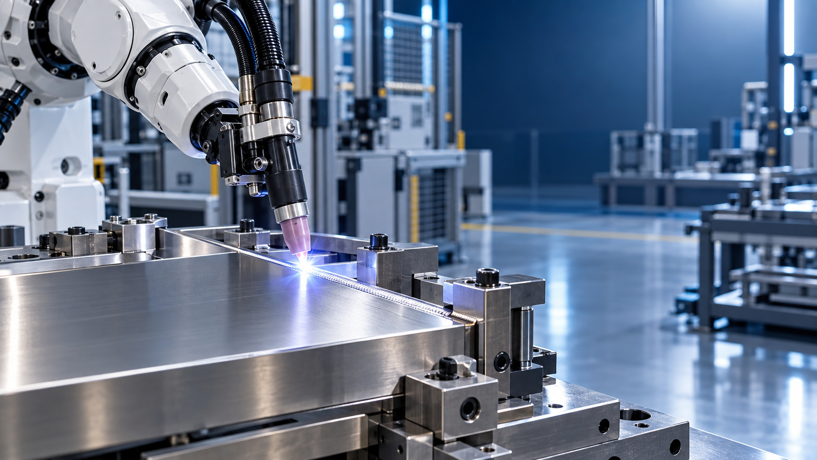
A robotic TIG welder is the right choice for thin stainless steel when the weld must be visually clean, dimensionally stable, and repeated across enough similar parts to justify controlled automation. The strongest fit is not every thin-gauge job. It is a family of parts with stable joint geometry, reliable fit-up, and quality requirements that expose the normal variation of manual welding: inconsistent bead width, heat tint, distortion, incomplete fusion at starts and stops, or rework caused by uneven penetration.
Thin stainless steel reacts quickly to small changes in heat input. A minor shift in arc length, torch angle, travel speed, or joint gap can alter the weld profile and the surrounding heat-affected zone. TIG welding offers precise arc control and clean results when shielding is maintained correctly. Robotic motion makes that control repeatable, provided that the workpiece reaches the cell in a repeatable condition.
Production Conditions That Support Automation
Part volume matters, but repetition matters more. A low-volume component with several identical weld seams may suit a robotic cell better than a high-volume product with constantly changing dimensions and fixtures. The robot gains value when a qualified welding program can be reused without frequent correction. Repeated enclosures, food-processing assemblies, instrument frames, cabinets, tanks, thin-wall tubular structures, and formed stainless subassemblies are common examples.
A robotic TIG welder is particularly appropriate where manual results vary between shifts or between welders. That variation is often visible before it becomes a mechanical defect. On brushed, polished, or exposed stainless surfaces, inconsistent color and bead contour can create substantial finishing work. When the component must remain visually uniform after welding, the ability to hold torch position, travel speed, current transitions, and overlap length provides a practical advantage.
The joint must also be accessible. TIG robotics performs best when the torch can approach the seam with adequate clearance for the gas cup, filler wire path, and any seam-tracking equipment. Deep internal corners, obstructed flanges, dense fittings, and narrow channels may require complex robot orientations or special torches. If access changes along the path, a program that looks feasible in a CAD review may still be difficult to run without collision risk or unstable shielding coverage.
Thin Stainless Steel Is a Heat-Control Problem
Stainless steel sheet does not need to be extremely thin before distortion becomes the deciding issue. Flat panels, long seams, shallow formed sections, and assemblies with cosmetic outer faces can move or buckle even when the weld itself is sound. The concern is not simply peak amperage. Total heat delivered per unit length, arc dwell at corners, tack-weld spacing, clamping restraint, and cooling between seams all affect the final shape.
Robotic TIG welding can limit variation in these inputs. A programmed current ramp reduces the abrupt heating and crater formation associated with poorly managed starts and stops. Stable travel speed avoids local overheating, while a consistent torch-to-work distance supports a predictable arc. Pulsed current may reduce average heat while retaining enough peak energy for fusion, but pulse settings should not be selected as a universal distortion cure. Excessive pulsing can produce an uneven bead appearance, complicate filler addition, or mask an underlying fit-up problem.
Distortion should be assessed at the assembly level. A narrow butt weld in a small stainless panel may remain straight with simple backing and clamps. The same seam placed near a folded edge can pull the flange out of tolerance. A robot repeats the programmed heat pattern very well; it will also repeat a distortion pattern very well. Fixture design and welding sequence therefore need to be validated before treating automation as the correction.
Heat Tint Is Not Only a Cosmetic Issue
Discoloration around a stainless weld reflects exposure to heat and oxygen. The color itself does not prove that the weld is defective, but it indicates that shielding, purge quality, surface condition, or thermal exposure deserves attention. On surfaces intended for corrosion-sensitive service or a high-grade finish, dark heat tint may require cleaning or post-weld treatment. A robotic cell improves consistency only when the gas system is equally controlled.
Gas coverage must remain stable through ignition, welding, crater fill, and post-flow. Drafts around an open cell, a damaged cup, contaminated consumables, or a torch orientation that exposes the molten pool can all create inconsistent color despite correct robot coordinates. For closed sections and full-penetration joints, backside protection must be considered separately. Shielding at the torch does not protect the root side. Purging should be planned around internal volume, venting, sealing method, and the point at which welding begins, rather than treated as an added hose connection.
Fit-Up Determines Whether Programming Holds
Many robotic TIG welding projects struggle because the proposed program assumes an ideal joint while upstream cutting, forming, and fixturing produce variable gaps. Thin stainless does not tolerate this mismatch well. A gap that is harmless in a manual process can require more filler, slower travel, altered current, or a different torch position. When variation exceeds the process window, the robot cannot use judgment in the same way a skilled manual welder can.
Before selecting equipment, examine actual parts from normal production rather than nominal drawings alone. Measure joint gap, edge alignment, flange angle, seam location, and part-to-fixture repeatability across multiple batches. Include material from different coils or suppliers if those sources are used. Stainless sheet thickness, springback after bending, laser-cut edge condition, and formed-feature location can shift enough to affect the weld path.
Joint preparation is often more influential than adding sophisticated sensing. Clean, burr-free edges give a TIG arc a more predictable path. Oil, marking residue, adhesive film, oxide, and embedded ferrous contamination can create porosity, unstable arc behavior, or staining. When a laser-cut edge has substantial oxide or irregular dross, the problem should be addressed before welding rather than compensated through increased current.
- Rigid location points: Datum surfaces should seat the part consistently without forcing a thin panel into a distorted condition.
- Clamp placement: Restraint near the seam can control movement, but excessive local clamping may hide springback until the part is released.
- Tack strategy: Tack location and size must be repeatable because every tack becomes part of the robot's thermal cycle.
- Gap management: If production gaps vary, define whether the process will use filler wire, seam tracking, tighter upstream tolerances, or a combination of these measures.
Seam tracking is useful when part variation is small but unavoidable. It should not be specified as a substitute for unstable fixtures. Through-arc tracking, tactile searching, laser-based sensing, and vision systems each have practical limits around reflective stainless surfaces, narrow joints, and changing joint preparation. The evaluation should identify the expected size and direction of variation first, then select sensing only where it addresses that variation.
Choosing the TIG Process Configuration
Autogenous welding, without filler wire, is attractive on closely fitted stainless joints because it simplifies the cell and produces a narrow bead. It is suitable only where joint fit-up remains tight and fusion requirements are met without added metal. Autogenous seams have little tolerance for gaps, edge mismatch, or poor restraint. They can also become concave if heat input and joint condition are not balanced.
Cold-wire or conventional filler-wire feeding expands the acceptable fit-up range and can improve weld shape, but it introduces another synchronized variable. Wire position must be stable relative to the leading edge of the weld pool. A poorly aligned wire can disturb the arc, cause intermittent deposition, or contaminate the tungsten. Wire cleanliness, spool handling, liner condition, and feeding consistency deserve the same attention as the robot path.
Direct current electrode negative is commonly used for austenitic stainless steel. The exact current range, tungsten selection, cup size, gas flow, and pulse schedule must be established through procedure trials for the actual joint and material condition. Selecting these values from sheet thickness alone is unreliable because thermal mass changes at flanges, corners, lap joints, and attachments. A thin wall joined to a heavier fitting needs a different heat balance from a uniform sheet butt joint.
Orbital-style motion is sometimes considered for cylindrical parts. Where the geometry is truly consistent and the seam is circumferential, a dedicated orbital arrangement may be simpler than a general six-axis robot. A multi-axis robot becomes more attractive when a single fixture holds several seams, when components vary in orientation, or when the torch must follow formed features and compound paths.
Quality Targets Should Be Defined Before Cell Design
A robotic welding proposal should be judged against measurable acceptance criteria, not the broad expectation of “better consistency.” Define the required weld profile, permissible undercut, root condition, penetration evidence where relevant, allowable distortion, surface finish after cleaning, and inspection method. A cosmetic stainless product may reject a faint color variation that is acceptable on an internal structural bracket. A liquid-containing assembly may focus on leak-tightness and root continuity. These are different process targets and may require different fixtures, purging arrangements, and cycle times.
Inspection access needs to be included in the fixture layout. A fixture that produces excellent repeatability but blocks visual examination, dimensional gauges, or leak-test connections creates delays outside the welding cell. If post-weld brushing, pickling, passivation, or mechanical finishing is planned, ensure that the robot produces a bead profile compatible with that downstream operation. A narrow uniform bead is not automatically easier to finish if it sits in a corner that cannot be reached by the finishing tool.
Where Robotic TIG Is a Poor Fit
Automation is difficult to justify when parts arrive with broad dimensional variation, when the mix changes faster than fixtures and programs can be prepared, or when the work contains many short, inaccessible, one-off seams. It is also a weak choice when the actual bottleneck is upstream forming accuracy, material preparation, or inspection turnaround. In those situations, a robotic cell can make the limitation more visible without removing it.
Very short welds deserve special scrutiny. The time spent loading, locating, searching, clamping, initiating the arc, and unloading can exceed the arc-on time. A robot may still be appropriate when several short welds are combined in one fixture or when manual quality is unacceptable, but the cycle should be evaluated as a complete handling sequence.
Thicker structural fabrication belongs to a different automation problem. A system such as a Heavy automatic h beam line is designed around beam conveying, turning, assembly, welding, straightening, and downstream structural processing. Those functions are valuable for large H-beam workflows, yet they do not replace the fine torch control, stainless shielding discipline, compact fixturing, and low-heat sequencing required for thin-gauge TIG work.
Prove the Process With Production-Representative Parts
A meaningful trial uses actual joint preparation, surface finish, material thickness range, fixtures, and anticipated weld sequence. Test coupons establish a starting point, but they rarely reveal assembly distortion, access problems, part loading variation, or heat effects at formed features. The trial should include starts and stops, corners, seam intersections, changes in orientation, and the first parts after a fixture change.
Record more than welding parameters. Capture the part location method, clamping order, tack condition, filler identity where used, gas delivery arrangement, torch consumables, and cleaning state. When a defect appears later, this record separates a weld-program issue from an incoming-part or handling issue. It also makes qualified programs more transferable between fixtures and future production batches.
The correct decision follows from that evidence. Robotic TIG welding earns its place when repeatable parts, controlled fit-up, reachable joints, and a clear finish or distortion target exist together. Where those conditions are absent, improving preparation and fixturing first will usually produce a more reliable basis for automation.
search
Products Navigation
Send Us A Message