




How robotic TIG welding reduces distortion in precision weldments
How Robotic TIG Welding Reduces Distortion in Precision Weldments
For project managers responsible for tight tolerances, rework costs, and delivery schedules, weld distortion can quickly disrupt precision fabrication. A frame that leaves the fixture flat may twist after the final pass. A thin stainless enclosure may develop a visible oil-can effect. A machined flange can lose alignment with its mating part after a circumferential weld. These are not minor shop-floor inconveniences; they can create downstream machining delays, failed fit-up inspections, and difficult conversations about who absorbs the correction cost.
Robotic TIG Welding provides a practical way to control one of distortion’s main causes: inconsistent heat application. It does not make the thermal behavior of metal disappear, and it cannot compensate for poor joint design or weak fixturing. What it can do is make heat input, torch angle, travel speed, arc length, sequence, and interpass timing far more repeatable than a process that depends entirely on manual technique. In precision weldments, that repeatability is often the difference between a predictable process and a recurring rework problem.
Why distortion remains difficult to manage
Distortion occurs because the weld zone expands as it is heated and contracts as it cools. The surrounding base material restrains part of that movement, leaving residual stresses that can pull a component out of shape. The risk rises when the weld is long, the section is thin, the assembly is asymmetrical, or heat is concentrated on one side of a structure. Stainless steel, aluminum, thin-gauge carbon steel, and precision-machined assemblies can all be sensitive, although the exact behavior depends on alloy, thickness, joint preparation, restraint, and weld procedure.
The problem is usually cumulative. One individual weld pass may look acceptable, but several passes on the same side of a panel or tubular assembly can build enough shrinkage to move critical dimensions. In a low-volume fabrication job, an experienced welder may correct the sequence by instinct. That can work well, but it is difficult to reproduce across shifts, operators, or repeat orders. When a project includes hundreds of similar parts, small variations become a quality-management issue rather than a craft issue.
TIG welding is often selected because it offers a clean, controllable arc and good visibility of the weld pool. Yet manual TIG can still produce inconsistent results if torch movement, filler addition, or pause time varies. Even a skilled operator may naturally slow down around corners, bridge a slightly wider gap, or spend extra time correcting fit-up. Those adjustments add heat precisely where the part may be least able to tolerate it.
The control points that make robotic TIG effective
The strongest distortion-control benefit of robotic TIG welding comes from process stability. A programmed cell can maintain a defined travel speed along straight runs, radii, circular seams, and repeated joint features. It can also hold a consistent torch-to-work distance and torch angle. These details matter because they influence arc energy distribution and weld bead geometry. When the bead profile remains stable, the associated shrinkage is more predictable.
A robot also supports more disciplined control of current pulsing, start and finish ramps, filler-wire feeding, and weave motion where the procedure requires them. Pulsed TIG is not automatically the best answer for every weld, but it can help manage the weld pool on thin or heat-sensitive material when the parameters have been properly developed. The useful principle is straightforward: apply enough energy to achieve the required fusion and penetration, but avoid depositing unnecessary heat into the assembly.
For project planning, it helps to distinguish between low heat input and controlled heat input. Reducing amperage without considering travel speed, joint gap, material condition, and penetration requirements can create incomplete fusion or unstable bead formation. The goal is not simply to run colder. The goal is to use a qualified, repeatable procedure that keeps the heat-affected zone and thermal cycle within an acceptable range for the part.
Repeatability improves the value of pre-set weld sequences
Sequence planning is one of the most underappreciated distortion controls. A robotic system can execute balanced stitch patterns, alternating sides, back-step sequences, or symmetrically placed welds with the same order every cycle. This is particularly useful on cabinet structures, instrument housings, machine frames, precision brackets, and fabricated assemblies with several welded mounting points.
Consider a rectangular weldment with two long seams and several short stiffener welds. If both long seams are completed in the same direction before the stiffeners are added, the assembly may pull toward one side. A better sequence may divide the welds into shorter segments, alternate opposing sides, and allow planned cooling between thermally concentrated operations. The precise sequence must be proven on the actual design, but once it is established, robotic execution prevents it from drifting because one operator prefers a different working pattern.
This is where Robotic TIG Welding is most useful in a production environment: it converts a known good welding strategy into a repeatable process. A project team can evaluate first-off parts, measure the resulting geometry, adjust programs or fixtures, and then release a stable method to production. Manual welding can follow the same discipline, but it is harder to maintain when workload, staffing, and shift conditions change.
Fixturing is not optional
Automation is sometimes expected to solve distortion by itself. In practice, the robot can only repeat the conditions it is given. If components enter the fixture with variable gaps, inconsistent tack welds, or inadequate clamping, the robot may repeat a poor result very efficiently. Before specifying a robotic TIG cell, review how the part is located, how thermal movement is restrained, and whether clamps interfere with torch access or gas coverage.
A good fixture does not necessarily mean maximum restraint. Over-clamping can introduce problems of its own, including difficult release after welding or stress concentration in a thin component. The fixture should locate critical datums, support the part close to the weld where practical, and allow controlled shrinkage in non-critical directions. For assemblies that require post-weld machining, it is often worth discussing which surfaces should remain stable and which can be left with machining allowance.
Tack weld quality deserves the same attention. Large, irregular tacks add heat before the programmed weld begins and can pull components out of position. Their size, spacing, and placement should be included in the fabrication plan. If tack welding remains manual, use clear instructions and gauges where necessary; otherwise, variation at this stage can undermine the benefits of the automated final weld.
Rotating cylindrical workpieces into the best welding position
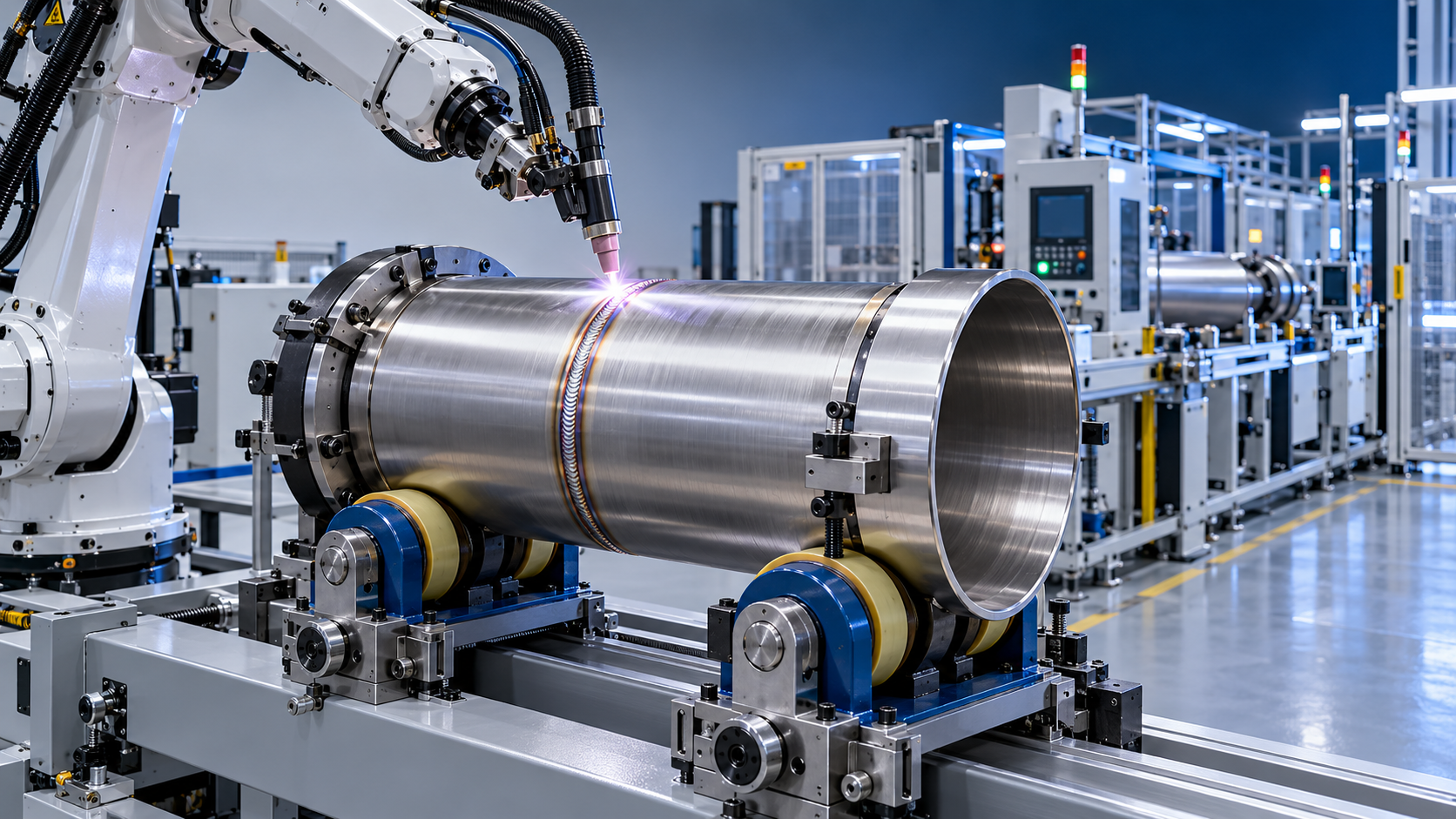
For pipes, pressure-vessel shells, cylinders, and other round assemblies, distortion control is closely connected to positioning. A seam welded in a stable flat or near-flat position is generally easier to control than one that forces the torch to work through changing orientations. Keeping the joint under the torch through controlled rotation can support a more uniform bead and reduce the tendency for operators or programs to compensate inconsistently around the circumference.
In this type of setup, a Bolt adjusting welding rotator can be integrated with the welding station to rotate cylindrical workpieces at a controlled speed. The available XHGK range covers rated loads from 2 to 800 tonnes, while its VFD-controlled rotation speed is specified at 100 to 1000 mm/min. For a project manager, the important point is not the broad capacity range alone. It is whether the selected rotator matches the actual vessel diameter, loaded weight, center-of-gravity condition, wheel arrangement, and welding sequence.
The line speed of the listed rotator series is 6 to 60 m/h, with forward, reverse, and speed-setting functions available through a remote hand control box. That range may suit many circumferential welding tasks, but synchronization between workpiece rotation and robot travel must be checked during process development. A mismatch can alter overlap at the weld start and stop, affect bead consistency, and create localized heat accumulation. Those areas are often where circular components show the first signs of distortion or surface irregularity.
Where automation has the clearest case
Robotic TIG is usually most compelling when a manufacturer has repeated parts, defined quality expectations, and a distortion-related cost that is visible in the project. That cost may be post-weld straightening, extra machining, fit-up rejection, cosmetic repair, or schedule risk at final assembly. The business case becomes weaker when every component is a one-off and fixturing or programming time cannot be recovered. It also becomes weaker when upstream cutting and forming tolerances are so variable that the robot constantly encounters changing joint conditions.
The practical decision is not “robot or skilled welder.” Many successful fabrication operations use both. A robot handles stable, repetitive seams where consistency matters most, while qualified welders manage prototypes, repair work, complex access conditions, and assemblies with high variation. This division allows skilled labor to be used where judgment genuinely adds value rather than where the same precise motion must be repeated all day.
For equipment projects involving laser cutting, CNC machining, bending, rolling, and automated welding, process handoffs should be reviewed early. A welding robot cannot compensate indefinitely for a flange that arrives with a changing bevel, a formed part with inconsistent springback, or a tube end that is not square. Companies such as Wuxi Samgins International Trade Co., Ltd., which supplies automatic welding equipment alongside CNC cutting, machining, forming, and beam-production equipment, are often asked to assess the line as a connected process rather than as isolated machines. That is the right conversation to have when dimensional control is the real requirement.
A sensible implementation path
Start with the weldment that causes the most repeatable pain, not necessarily the largest part. Select an assembly with enough volume to justify fixture and program development, clear dimensional acceptance criteria, and a known rework history. Record dimensions before welding, immediately after welding, and after cooling. Measure the same references on several samples rather than relying on one “good” part. This establishes whether the distortion pattern is stable enough to improve through sequence and parameter control.
Then develop the cell around the whole operation: material presentation, tack condition, clamping, torch access, shielding gas coverage, wire supply if used, seam tracking requirements, and part removal. The welding procedure should be reviewed by appropriately qualified personnel, especially where code work, pressure containment, or customer-specific acceptance requirements apply. CE-marked equipment may be relevant for European installation, but machine conformity is separate from qualification of the weld procedure and the finished component.
Do not overlook maintenance. A worn torch consumable, contaminated tungsten, inconsistent gas supply, or slight fixture damage can change arc behavior long before an obvious defect appears. Establish simple checks for torch condition, fixture datum surfaces, clamp force, rotation smoothness, and program revision control. These are routine disciplines, but they protect the very repeatability that justified automation.
The real reduction comes from predictability
Robotic TIG welding reduces distortion not by eliminating heat, but by making heat application deliberate and repeatable. Stable motion, programmed sequencing, controlled positioning, and suitable fixturing give engineering teams a better chance to predict how a weldment will move. That predictability makes it easier to set machining allowance, protect critical datums, plan inspections, and avoid late-stage correction.
Before committing to a system, review the component geometry and the full production route rather than focusing only on robot reach or welding current. If the joint fit-up, restraint strategy, rotation method, and acceptance dimensions are understood, automation can turn a difficult distortion problem into a managed manufacturing variable. If they are not, the robot will simply reveal the weaknesses of the existing process faster.
search
Products Navigation
Send Us A Message