




How to prevent electrode contamination in robotic TIG welding
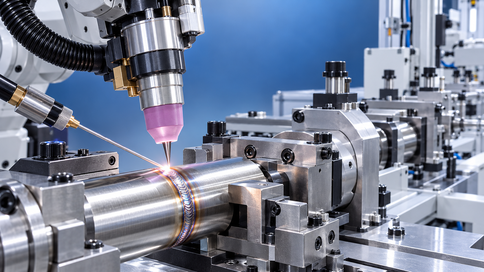
A contaminated tungsten electrode is one of the fastest ways to turn a stable robotic TIG welding process into a source of inconsistent arc starts, poor bead appearance, inclusions, and unnecessary stoppages. In an automated cell, the problem is often harder to diagnose than in manual TIG welding because the robot repeats the same programmed motion while several small variables—torch height, wire position, gas coverage, part fit-up, and fixture condition—can drift independently.
Preventing electrode contamination in Robotic TIG Welding starts with treating the tungsten as a process-control point, not as a consumable that is simply replaced after a bad weld. A clean electrode should maintain a consistent tip geometry, stay outside the molten puddle and filler wire path, and remain continuously protected by clean shielding gas. When those conditions are controlled, tungsten life improves and weld quality becomes more repeatable.
First identify what is contaminating the electrode
Not all dark, rounded, or damaged tungsten tips have the same cause. Regrinding an electrode without identifying the contamination source may restore production briefly, but the same fault will usually return.
- Contact with the weld pool: The electrode dips into the molten metal because the torch is too low, the workpiece is out of position, or the programmed path does not match the actual joint.
- Filler wire touching the tungsten: This is common in automated wire-fed TIG cells when wire aim, wire stickout, feeding timing, or robot-to-wire synchronization is incorrect.
- Oxidation from inadequate gas shielding: A poor gas envelope can discolor and erode the electrode even when it never physically touches the workpiece.
- Mechanical collision: The torch can strike a tack weld, fixture, part edge, distortion, or accumulated spatter from a neighboring operation.
- Surface contamination on the part: Oil, moisture, paint, oxide, grinding residue, or cutting fluid can destabilize the arc and transfer contaminants into the weld zone.
The appearance of the tungsten provides useful clues. A rounded or balled tip on a process intended for a pointed electrode often indicates excessive heat input, unsuitable polarity or settings, or repeated brief contact with the puddle. A black or grey oxidized tip points more strongly toward shielding gas problems. A chipped tip or a tungsten with visible metal attached to it is more likely to have contacted the workpiece or filler wire.
Keep the programmed torch position tied to the real joint
Robotic repeatability does not compensate for variation in the part. If workpieces arrive with inconsistent dimensions, heat distortion, poor fit-up, or changing tack-weld profiles, a robot can reproduce an electrode-dip event with excellent precision. This is why contamination should be investigated at the joint and fixture before adjusting welding parameters.
Start by checking the actual tungsten-to-work distance at several points along the weld path, including the start, corners, transitions, and end crater. Compare the programmed path with the position of a correctly loaded part. A path that is safe on a nominal sample may become unsafe where a seam rises, a flange springs upward, or a tack bead stands proud of the joint.
Tool center point accuracy also deserves attention. After replacing a torch body, collet, gas lens, electrode, or torch neck, the physical location of the tungsten tip can shift. Even a small shift matters when welding narrow joints or when the electrode is set close to the work. Recalibrate the TCP whenever the torch assembly changes, and confirm that the robot program references the actual tungsten tip rather than an assumed point near the torch.
Fixture condition is part of this check. Loose locators, worn clamps, heat-affected supports, and debris beneath a component can move the weld joint enough to cause occasional contact. A contamination event that occurs only on some cycles or only after several parts often points to inconsistent part seating rather than an arc-setting problem.
Use clearance deliberately, not excessively
Increasing arc length may seem like an easy way to avoid contact, but too much clearance reduces arc control and can widen the heat-affected zone. The goal is a repeatable working distance that provides enough margin for normal part variation without sacrificing joint access or arc stability. The correct margin depends on joint geometry, tungsten diameter, electrode extension, filler-wire use, and the accuracy of the cell.
Where part variation cannot be reduced sufficiently, seam tracking, touch sensing, laser profiling, or adaptive path correction may be justified. These systems are most useful when they solve a demonstrated positioning problem. They will not correct wire interference, poor gas coverage, or a dirty component surface.
Wire position is a frequent source of hidden contamination
In wire-fed robotic TIG welding, the filler wire must enter the leading edge of the weld pool consistently without crossing the electrode axis. A wire that is too high can touch the tungsten. A wire that is too low may scrape the workpiece or freeze before it reaches the puddle. A wire delivered too far forward or backward can disturb the puddle and create unstable transfer conditions.
Inspect wire alignment with the arc off and the robot positioned at representative weld locations. It is not enough to inspect only the start point. Changes in robot wrist orientation, torch angle, or wire feeder mounting can alter the apparent relationship between wire and tungsten as the robot moves through the path.
- Confirm that the wire guide is secure and free of wear that allows the wire to wander.
- Check wire straightness near the torch. Residual cast or helix can shift the wire path as it advances.
- Set wire stickout consistently; a long unsupported length is more likely to vibrate or deflect.
- Verify feed start and stop timing, especially during arc initiation, corners, and crater filling.
- Keep the wire clean and dry. Contaminated filler can introduce material into the puddle and make the arc less predictable.
Wire contact can be intermittent enough that operators see only occasional electrode damage. Reviewing the fault in slow-speed dry runs is often more productive than immediately changing current, travel speed, or pulse settings. The important question is whether the wire remains in a controlled relationship to the puddle throughout the entire motion.
Protect the tungsten with stable shielding gas coverage
Shielding gas problems do more than discolor the weld. Once the electrode oxidizes, its emission characteristics and tip shape change, making arc starts less reliable and increasing the chance of further contamination. Gas coverage should therefore be checked as a complete system: source supply, regulator, hose, torch connections, consumables, cup condition, flow setting, and surrounding air movement.
Leaks are not always obvious. A small leak at a torch connection or damaged hose can pull air into the shielding stream without causing a dramatic change in flowmeter reading. Inspect connections, seals, collet bodies, gas lenses, and torch heads whenever oxidation appears unexpectedly. A blocked or contaminated gas diffuser can also create an uneven gas envelope even when the measured flow rate looks normal.
More gas is not automatically better. Excessive flow can create turbulence and draw surrounding air toward the arc, particularly with a large cup, awkward torch angle, or cross-draft. Set flow according to the torch configuration, material, joint access, and cell conditions, then confirm the result by observing electrode and weld behavior. If the electrode oxidizes immediately after arc stop, review post-flow duration as well as flow quantity.
Robotic cells may have local causes of air disturbance that are absent during bench testing: extraction systems, enclosure gaps, cooling fans, nearby automation, or operators opening doors during troubleshooting. Check gas protection with the cell operating in its normal production condition. A process that works with the enclosure open and extraction reduced may fail once the full ventilation system is running.
Prepare the electrode correctly and protect it after preparation
Tungsten preparation affects both arc behavior and contamination resistance. The electrode grade, diameter, tip angle, and tip finish should suit the welding procedure and power source. The process should use a documented preparation standard so every replacement does not introduce a different arc shape or current-carrying condition.
For applications requiring a pointed electrode, grind lengthwise along the electrode axis rather than across it. Longitudinal grinding marks help maintain a focused arc; circumferential scratches can encourage arc wandering. Use a dedicated grinding method for tungsten rather than a general shop grinder that may transfer steel, aluminum, abrasive residue, or other material to the electrode.
Handle prepared electrodes with clean gloves or clean tools. Finger oils and shop dirt are small contaminants, but automated TIG processes often operate with narrow process margins. Store prepared electrodes in a clean, protected holder instead of leaving them on a workbench or near grinding dust.
When an electrode is contaminated by contact with the weld pool or filler wire, do not simply break off the visibly damaged end and resume production unless the remaining geometry is known to be acceptable. Remove enough material to eliminate transferred metal and heat-affected discoloration, then regrind to the approved shape. Continuing with a contaminated tip can turn a minor event into repeated poor starts, arc wandering, and defects over multiple parts.
Control the workpiece before it reaches the cell
A clean tungsten cannot compensate for dirty incoming material. Oils, machining coolant, marker residue, moisture, adhesive films, and heavy oxide can destabilize the puddle and leave deposits on the electrode. This is especially relevant when welded components come from several preceding operations or spend time in shared material-handling areas.
Define a practical cleaning requirement for the weld zone, including how far from the joint surfaces must be cleaned. For aluminum, stainless steel, and other oxidation-sensitive materials, surface preparation may need to address oxide as well as oil. Avoid using tools or brushes that transfer foreign material between alloys. The cleaning method should be compatible with the welding procedure and must leave the part dry before it enters the fixture.
Part design and upstream manufacturing choices also affect weld-cell cleanliness. Burrs, distorted cut edges, poorly placed tacks, and inconsistent formed edges create obstacles that can force the tungsten too close to the joint. In a production line that combines fabrication processes, evaluate whether upstream steps are producing debris or geometry variation that reaches the TIG station. For example, cold-forming equipment such as the Z28-650 thread rolling machine can avoid chips during thread production, but parts still need to be managed so coolant, handling residue, and dimensional variation do not migrate into a precision welding operation.
Build contamination checks into recovery procedures
The most effective response is not a detailed troubleshooting guide that appears after quality has already failed. A robotic cell should have clear stop-and-check conditions. Examples include an arc-start failure, a sudden change in arc voltage behavior, visible electrode discoloration, a collision alarm, wire-feed fault, or a weld appearance change at a known stable program.
After any suspected dip or collision, the operator should inspect the tungsten, cup, gas lens or collet body, wire guide, and immediate fixture area. Replacing only the electrode can miss a bent torch neck, cracked ceramic cup, shifted wire guide, or damaged diffuser. The corrective action should restore the complete torch geometry and gas path before the cell is restarted.
It is also useful to record the location of recurrent contamination events: weld start, corner, seam transition, final crater, or a specific fixture position. Patterns usually point toward one of three areas—robot motion and access, incoming part variation, or wire and gas hardware. That information is far more actionable than recording “bad tungsten” as a general maintenance issue.
Do not solve every contamination event with more current or more gas
Operators sometimes compensate for a weak or unstable arc by increasing current, changing pulse settings, or raising gas flow. Those adjustments may hide the symptom temporarily, yet they can worsen electrode overheating, turbulence, or puddle control. Parameters should be adjusted only after physical contact risks, gas integrity, electrode condition, and workpiece cleanliness have been checked.
A stable robotic TIG process leaves visible evidence: the tungsten keeps its intended shape, the arc starts consistently, the weld pool remains predictable, and replacement intervals are not driven by unexplained damage. When contamination becomes frequent, inspect the sequence from part loading through final post-flow. The cause is usually a controllable mismatch in that sequence, rather than an unavoidable cost of automated welding.
search
Products Navigation
Send Us A Message